I think all the horror stories about PayPal happened before ebay took over Paypal. They seem to have gotten thier act together since ebay has taken the over.
Being a little on the lazy side, is their an output board you could offer us also? BTW, thank you for allowing us to take advantage of you PCB design skills.
The boards are great. The only thing I would change would be try to place the diff pair closer together to share a small heatsink.
As for driver boards, use your skill here and do point to point and spread the fets over the heat sink.
I'll buy 4 or 6 more on principle.
As for driver boards, use your skill here and do point to point and spread the fets over the heat sink.
I'll buy 4 or 6 more on principle.
Put me down for 4 boards. I'll save the originals for when Brian gets famous than sell them on eBay for a huge profit.😀
Count me in for a pair.
I'm in no hurry, but I plan on having a crack at an Aleph sometime so I may as well get some boards.
Will you ship to Aus?
Anyone know if there is likely to be another group buy of Aleph-X boards?
Mark
I'm in no hurry, but I plan on having a crack at an Aleph sometime so I may as well get some boards.
Will you ship to Aus?
Anyone know if there is likely to be another group buy of Aleph-X boards?
Mark
Brian, thanks for posting the pic of the layout.
Bikeman, I'll ship anywhere you want - as long as you pay for it 🙂
I was under the impression that Brian already had an output board done, but perhaps not. I would definetly be interested in ordering some as well. I have seen some boards in projects at PassDIY, and if someone wants to send me some Gerbers, I'm willing to organize a group buy for those as well. Just let me know.
It seems that the diff. pair could be moved closer together without much work. Right now, as is, I had just planned on adding an aluminum L-bracket to thermally couple them together.
I would also like to make another suggestion/comment. I don't really like the fact that the high-current power supply feeds for the output boards are running through that little trace on the driver board. Wouldn't it be better to have a direct connection from the power supply via a decent gauged wire? If there wasn't a soldermask, one could just solder a piece of bare wire along that trace to beef it up, but with a soldermask... I'm concerned. Perhaps the power supply connection to the rail voltages on the left side of the board could be moved closer to the connections to the output boards. Then the user could put a little extra wire through the holes and solder them directly to each other to pass the high current. Just a suggestion - any thoughts?
Count me in for 2 pairs. For payment, let me know on a total cost to ship to Canada by regular mail.
Is there some documentation on how to wire the PCBs in different Aleph wattages/models?
Also, do you accept US$ cash by mail? I'm not particularly fancy on the transaction cost that Paypal or even money orders have.
BQ
Is there some documentation on how to wire the PCBs in different Aleph wattages/models?
Also, do you accept US$ cash by mail? I'm not particularly fancy on the transaction cost that Paypal or even money orders have.
BQ
Super_BQ said:Count me in for 2 pairs. For payment, let me know on a total cost to ship to Canada by regular mail.
Is there some documentation on how to wire the PCBs in different Aleph wattages/models?
BQ
If you look over the passlabs service manuals for the aleph, you will see the differences in the models:
http://www.passlabs.com/aleph.htm
Ideally, you could design any wattage aleph, by changing the power supply levels, and setting the bias current to what is needed for your load. (within reason... I question the idea of making a high power aleph with 100v rails or something crazy like that... would need water cooling, and a hell of a lot of power. The 200w aleph 1.2 has 60v rails, and draws 500w of power per monoblock)
--
Brian
Post more suggestions for ideas to change the Aleph PCB, and I can redo the design in a week or so.
Here are some considerations for the board design that I have considered:
1.) Does anyone object to a 2-layer board design with plated through holes? This could allow for a sizable reduction in board size, along with shorter traces between components.
2.) Would a ground plane be preferred? This could easily be done with the change to 2 layers.
3.) How many resistors are desired to be on board for the output stage?
4.) Should the board have the option of having a single pair of output devices on board, leaving the option for a Mini-A (10w aleph).
5.) Is it a good idea to couple together the diff pair, without heatsinks, (back to back), as for best thermal tracking?
6.) What gauge wire is to be used for wiring to the output devices? Would making the spacing for terminal blocks preferrable?
That is all I can think of for now. If this discussion goes anywhere, a new layout can be worked out. I made a small Mini-A layout a week or so ago, and I am getting a couple of boards made for myself along with my dac boards. They are exactly 1/4 the size of the Aleph pcb (2"x3" instead of 4"x 6"). Pictures here:
http://www.diyaudio.com/forums/showthread.php?s=&threadid=20912
This is not a layout planned for a board order, as people seem to have trouble with SMD parts, and I did it the other weekend just to see if I SMD parts are feasible.
--
Brian
You could make the inputstage somewhat thermaly coupled through giving them a separate groundplane (they still need to be isolated from eachother thoug)
I did that in my version of your boards and also..the board was made smalare and for RN65 dales and cadock TO220 output
But still directly coupling the devices together would me much preferable ..althogh performance in this case may not be so dependet on ot.
/ micke
I did that in my version of your boards and also..the board was made smalare and for RN65 dales and cadock TO220 output
But still directly coupling the devices together would me much preferable ..althogh performance in this case may not be so dependet on ot.
/ micke
BrianGT said:Here are some considerations for the board design that I have considered:
1.) Does anyone object to a 2-layer board design with plated through holes? This could allow for a sizable reduction in board size, along with shorter traces between components.
2.) Would a ground plane be preferred? This could easily be done with the change to 2 layers.
3.) How many resistors are desired to be on board for the output stage?
4.) Should the board have the option of having a single pair of output devices on board, leaving the option for a Mini-A (10w aleph).
5.) Is it a good idea to couple together the diff pair, without heatsinks, (back to back), as for best thermal tracking?
6.) What gauge wire is to be used for wiring to the output devices? Would making the spacing for terminal blocks preferrable?
That is all I can think of for now. If this discussion goes anywhere, a new layout can be worked out. I made a small Mini-A layout a week or so ago, and I am getting a couple of boards made for myself along with my dac boards. They are exactly 1/4 the size of the Aleph pcb (2"x3" instead of 4"x 6"). Pictures here:
http://www.diyaudio.com/forums/showthread.php?s=&threadid=20912
This is not a layout planned for a board order, as people seem to have trouble with SMD parts, and I did it the other weekend just to see if I SMD parts are feasible.
--
Brian
Brian,
I do not want to be the one to cause you extra work. The board as it exists now is very nicely executed. If you want to put in the extra time to improve things, God bless ya. I think all of your suggestions are great. I especially like the suggestions about putting a ground plane in, the terminal blocks and adding the resistors to the board. Six of them would be ok for me. Again, thanks for stepping up to the plate for us.
Layout changes
Brian,
These are he changes I would like to see. Room for some larger 220uf axial with the ability to parallel some 1uf PP film caps. Next I would add some power supply filtering on the PCB for the +/- power supply. Next either remove the .47 ohm output resistors or widen the trace width. Also, cascode connection on the diff pair would improve the performance.
This would make a good start.
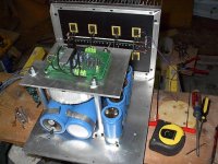
As they are, they sound stunning. I could come up with a hunderd Stereophile coined phrases, but I'm not The high power should not be run through the boards if your building a High power Aleph. The L bracket does great as a heat sink and thermal couple between diff pair. I bought 4 of the Hardvarian group order, but I'll for sure want at least 6 of these, upgrades or not. I added 12 gauge wire silver soldered over the high power traces in question, but I don't have a pic handy to attach.
Again, Thanks Nelson and Brian
Again, Thanks Nelson and Brian
Brian Donaldson said:As they are, they sound stunning. I could come up with a hunderd Stereophile coined phrases, but I'm not The high power should not be run through the boards if your building a High power Aleph. The L bracket does great as a heat sink and thermal couple between diff pair. I bought 4 of the Hardvarian group order, but I'll for sure want at least 6 of these, upgrades or not. I added 12 gauge wire silver soldered over the high power traces in question, but I don't have a pic handy to attach.
Again, Thanks Nelson and Brian
I am glad that you like the boards, and most of the thanks should go to Nelson, for his gracious support of this community 🙂
See if you can get a picture, I am curious as to how your bulked up traces look.
--
Brian
Hey Brian
If you're in Georgia, It's after 2:00AM and you should be sleeping.
It's a task to take a digital pic, down load it, scale it down, and post it, but I'll do it anouther day
If you're in Georgia, It's after 2:00AM and you should be sleeping.
It's a task to take a digital pic, down load it, scale it down, and post it, but I'll do it anouther day
Brian Donaldson said:Hey Brian
If you're in Georgia, It's after 2:00AM and you should be sleeping.
It's a task to take a digital pic, down load it, scale it down, and post it, but I'll do it anouther day
heh.. there isn't too much sleep during midterms... I expect to catch up this weekend.
I am actually still at school now, studying at the library, and taking a periodic break to grab some snacks and check my e-mail on my laptop.
--
Brian
- Status
- Not open for further replies.
- Home
- Amplifiers
- Pass Labs
- Aleph PCB group order