I tried to get some questions going in another thread, maybe I asked a bad question, or I’m too impatient, anyways hopefully someone here can help me out.
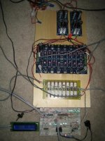
I’ve managed to put together an Aleph P1.7 clone using boards from KK-PCB. It works and sounds great aside from a slight hum which will hopefully go away with better grounding in a metal case. I also designed my own control system using a PIC to decode inputs from a remote and an optical encoder to control an attenuator, input selector and LCD.
This was a BIG effort, I didn’t even know what a PIC was when I started, and I’d never drawn a schematic or created or etched a board. It’s all done and working well, but I get a lot of POPS when the relays on the attenuator change. (I haven’t tested the input selector yet). The attenuator is straight out of the Aleph P1.7 service manual.
I’ve read a lot of posts suggesting that timing is the issue. But I get my biggest pop switching from no relays activated (output disconnected) to switching in the first resistor (8.06k).
From what I have read this would suggest a dc offset problem. I have an all single ended set up….for now. The –input to the preamp is shorted to ground, the –output is floating. There is 0.4 mV on the left channel between the + output and ground, and 0.2mV on the right. Is the cause for the big pop? If so what can I do to get rid of it?
I would really like to get this thing de-bugged and into a proper home.
Any help would be Greatly Appreciated.
Tvnorm
Heres the current mess:
Attachments
TV,
You should have no DC offset at the output. Certainly that will cause a
HUGE pop when you switch in the relays. The outputs are AC coupled,
no? How can you have a DC offset in that case? I'm having trouble
thinking how that can be if the circuit is correct. I think that there is
a problem with the output circuit. You need to fix that first. You may
damage your speakers or power amp if you allow a large DC offset
to be input to the PA. I strongly advise you to not use your preamp
until your DC offset is so small your voltmeter can't measure it.
I had a similar pop in my attenuator when switching but it was when
switching in and out the msb, not when switching in the first bit. I solved
that problem by switching off all the relays and then switching on the
new ON relays one by one from the lsb to the msb.
Congrats on finishing a large project. When you get this sorted out you're
going to enjoy your amp.
Sorry I can't be more helpful.
W.
Wayne, thanks for the replies.
I guess I have bigger troubles than I thought.
I suspected my el cheapo multimeter was aproaching its limits, so I went to the lab and used one of those multimeters with 6 digits after the decimal point or something ridiculous like that. I could not get a steady reading, it kept swinging back and forth +/-3mv or so.
So I hooked a scope up to and took some pictures:
Now I don't know for sure what any of this means I was just shown the basics on how to operate the scope. But I thinks it's not dc offset.
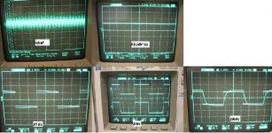
The pic labeled noise is what came out of the right channel +ouput with nothing hooked up but the scope, and the - input grounded. The R- and both the +/- output on the left channel, displayed a similar ouput but with not as strong of a wave form, i.e. there was more randomness to it, but it was pretty much the same. This noise would hover randomly between +/- a few mV most of the time and would jump as high as +/-5 mV on a few occasions.
Then there is the PS at 50V/div, and the square wave response at 20Hz, 2kHz, and 20kHz.
Can anyone tell me what is going on here?
I can put up better pictures if it would be helpful.
edit- I tried to measure the frequency of the noise, it varied between, "not found" and 10's of MHz
I guess I have bigger troubles than I thought.
I suspected my el cheapo multimeter was aproaching its limits, so I went to the lab and used one of those multimeters with 6 digits after the decimal point or something ridiculous like that. I could not get a steady reading, it kept swinging back and forth +/-3mv or so.
So I hooked a scope up to and took some pictures:
Now I don't know for sure what any of this means I was just shown the basics on how to operate the scope. But I thinks it's not dc offset.
The pic labeled noise is what came out of the right channel +ouput with nothing hooked up but the scope, and the - input grounded. The R- and both the +/- output on the left channel, displayed a similar ouput but with not as strong of a wave form, i.e. there was more randomness to it, but it was pretty much the same. This noise would hover randomly between +/- a few mV most of the time and would jump as high as +/-5 mV on a few occasions.
Then there is the PS at 50V/div, and the square wave response at 20Hz, 2kHz, and 20kHz.
Can anyone tell me what is going on here?
I can put up better pictures if it would be helpful.
edit- I tried to measure the frequency of the noise, it varied between, "not found" and 10's of MHz
Attachments
TV,
Sorry dude I messed up. You wrote you were getting DC offsets of
tenths of mV and my pea-szed brain was thinking tenths of volts.
An offset of that magnitude is probably just fine.
I'll see what I can think up from your pics.
W.
Sorry dude I messed up. You wrote you were getting DC offsets of
tenths of mV and my pea-szed brain was thinking tenths of volts.
An offset of that magnitude is probably just fine.
I'll see what I can think up from your pics.
W.
TV,
I'm thinking....
Here's what I see.
20 Hz: this is busted I think. We see the decay towards ground after the
intial attack but at 20 Hz it should look a lot more like a square wave
output than that. Seems like the C is too small or the R is too small.
20 kHz: Again we see a lot of rounding at the attack-side shoulder.
I don't thing it should look that rounded.
I can't say for sure though. I'd have to hook up my amp and see
what it does. I've never tested it beyond DC probing and what my
ear tells me.
Do you have a problem in your circuit somewhere? What happens if you
probe on the input to the output DC block caps ?
If you want to see what your PS is doing, set your scope to AC input
and it will show any spikes with your square wave signal. Using a DC
wave won't show much because you have to zoom out a lot.
Sorry dude I'm not coming up with much am I?
BTW at a couple mV DC you should be fine to connect your amp to
your power amp - ignore my previous cautions against this.
I definitely don't get much in the way of a pop when I switch in my
lsb.
W.
TV, are you sure that you don't have any DC from relay coils on the outputs? Did you mesure dc after the relays? Try to replace the whole relay atenuator with the 10K pot and then mesure the DC. If everything is fine, then you check your relay attenuator circut. Did you put blocking diodes on relay coils? I also use relay attenuator and everything works without any problems.
Wayne,
Thanks again for the help, and hopefully I'll make some progress soon.
Which C or R are you refering to here?20 Hz: this is busted I think. We see the decay towards ground after the intial attack but at 20 Hz it should look a lot more like a square wave output than that. Seems like the C is too small or the R is too small.
I agree, but I can't even begin to diagnose it.20 kHz: Again we see a lot of rounding at the attack-side shoulder.
I was hoping someone else would know, lol.Do you have a problem in your circuit somewhere?
This would mean at where the drains of the 610 and 9610 meet, before the 3 X 10uF in paralell? I'll check that out.What happens if you probe on the input to the output DC block caps ?
So thats how you do it, thanks for the tip. I scratched my head for a while on how to zoom in on the ripple.If you want to see what your PS is doing, set your scope to AC input
Thanks again for the help, and hopefully I'll make some progress soon.
smario,
I did all of those tests with the relay attenuator completely disconnected, right at the ouputs on the circuit board.
I'll do a comparo with the 10k pot also. I do have diodes on the relay coils.
I'm beginning to wonder if I have more than one problem here...
I did all of those tests with the relay attenuator completely disconnected, right at the ouputs on the circuit board.
I did do basic continuity tests on the relay board after I finished it, to make sure nothing was shorted, but I didn't measure for dc on the attenuator by itself. These are good ideas, I will recheck the attenuator board by itself more thoroughly to eliminate that possibility.TV, are you sure that you don't have any DC from relay coils on the outputs? Did you mesure dc after the relays?
I'll do a comparo with the 10k pot also. I do have diodes on the relay coils.
I'm beginning to wonder if I have more than one problem here...
This is good to hear, I will keep trying.I also use relay attenuator and everything works without any problems.
tvnorm said:Wayne,
Which C or R are you refering to here?
I agree, but I can't even begin to diagnose it.
I was hoping someone else would know, lol.
This would mean at where the drains of the 610 and 9610 meet, before the 3 X 10uF in paralell? I'll check that out.
So thats how you do it, thanks for the tip. I scratched my head for a while on how to zoom in on the ripple.
Thanks again for the help, and hopefully I'll make some progress soon.
TV,
The C and R are the ones on the output side of the amp. On the original
Pass Labs circuit schematic, it's eg C14, C15, C16 in parallel and R64
which holds the output at ground reference over time.
Probe on drain of Q19 = drain of Q18, that is the output referenced
at a high DC voltage. See if the square waves look better there. THen
calculate the decay time constant of 30 uF drained by 4k75 and see
if it matches your scope traces. Maybe it's fine. At least double check
the components there.
Do you have long traces of the relay control nets alongside the signal
nets? That could inject switching noise.
Good luck,
W.
Wayne,
Ok, I am feeling pretty dumb.
It turns out that the problem with the attenuator was a dc offset on the power amp input. The attenuator is perfect, with no pops whatsoever using the the method described by Russ White here:
http://www.diyaudio.com/forums/showthread.php?s=&threadid=81008&perpage=10&pagenumber=2
I had to run through the code with pencil and paper a few times before I got it, but it works great. I tried your method first (blanking and cascading up) but I still ended up with 4 or 5 pops (out of 100 settings-I'm picky).
I am still curious about those scope traces. I checked all of the components visually and they are correct, And according to my math the discharging of the capacitor matches the shape of the squarewave at 20Hz. Probing at the drains, the square wave at 20Hz is perfect.
Beginning around 2kHz the square wave front edge begins to round noticably, and eventually looks like It did in the 20kHz photo. This is true after the caps and at the drains before the caps.
I tested with a sine wave and that crazy square wave at 20kHz seems to be nothing more than phase shift. Neat, to see how that translates, but I'm still not sure its supposed to be there...
Any thoughts?
So it would appear that all is well, except for my power amp....
Thanks again for all the suggestions,
tvnorm
- Status
- Not open for further replies.
- Home
- Amplifiers
- Pass Labs
- Aleph P1.7 relay attenuator help needed