almost finished
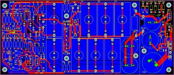
well I worked on it this weekend and the board is almost finished. I only need to rethink a few traces and add grounds, a carved out copper pour on the bottom layer; (trying to do a better job on the grounds than the last time on Juma's bf862 preamp for f5). btw this pcb was not easy since the relays and caps are all big and not forgiving in shapes as far as getting a nice placement. I put the function first, separated inputs from outputs and outputs from power as much as possible, thus the nice symmetry has been slightly sacrificed.
Updates:
final pcb dimensions with the 60V regulator added: 90mm(W) x 210mm(L). I drew a line and provided the pads for wires for those who decide to separate them, but there will be NO scoring line. The default application is dual mono and I will make all electrical connections across the line (do not want jumpers), and if you decide to separate you will have to cut the board (be careful not to get injured!!). if you need tips on "how to" check out youtube.
as stated before for grounding inputs/outputs (if used unbalanced) you will be using a 5V 4-pin Coto relay 9007-05-01. if you choose to use the version with no protection diode instead, (9007-05-00), for the relay in the middle I suggest you add a protection diode under the pcb straight between the pins 2&3 (and not use my diode footprint on the board because it is a bit farther than optimal). btw for all relays pin 1 is the one with the square pad.
p.s. you will notice that I left the pin 5 there for my 5-pin suplus stock relays and I will cut the 4-5 trace on the board to make my relays work (I did not want to be an a@%#$-- and make mine work and make everybody else use a jumper for theirs).
under Wima caps I put footprints for the cheapo option of Elna silmics with bypass film caps but NO TRACES to those pads (so wire additions would be required). i deleted them since they form big loops for picking up noise and would also break up my ground plane big time.
>>also note that ALL electrolitic caps have a footprint for adding a film bypass cap UNDER THE PCB!
PS section:
now some of you may not be happy but I used a 4-pin rectifier bridge (GBU4G) and left room behind it for a hsink if needed (probably an overkill). if you use individual diodes instead you will have to add them to that footprint and for 1 or 2 diodes it may not be all that pretty (sorry!). also for the first 2 paralel 1mF caps in the schematic I had to use a single 2,200uF/100V cap instead (snap in P:10mm 25x50mm(DxH); (mine is Panasonic ECO-S2AA222CA); the rest of them are all 1000uF/100V P:10mm. 20x36(DxH) (mine are Nichicons UVR2A102MRD6).
here is the picture of the boards (only the ground plane is missing):
Last edited:
Hi Koja
I appreciate your hard work but I have some questions, suggestions if it's possible ;
- jea, I'm the one that doesn't like the use of 4-pin rectifier bridge instead 4 diodes, but I can live with that...😀
- but I don't like the idea of using this 2200uF instead of 2x1000uF (or 4x1000uf total)
as I see you have space on PCB to place tham, just have to rearrange the look a little.
The reason, for using 4 of a sime kind is simple because we can get better price on sime item in larger quantities.
I will survive with any option
but it would be great if you could keep all those large capacitors on sime tipe
thanks
no room for two 1kuF caps or screw holes fall off the board. i could have done a little nicer job for myself doing dual mono, but I had to accommodate those who may choose to separate the regulator. I also left room on the inside of the rectifier for a hsink, (probably an overkill but I am not sure what to expect with those who may use one reg to drive more channels).
believe me, I spent enough time staring at all those circles and rectangles, reshaffling them only to find traces crossing each other or things getting close where they are not supposed to. just replace that pair with a 2.2kuF cap and call it done.
I will only one day manually trace everything to minimize the probability for an error, and add nice grounds, and that's gonna have to do it 🙄.
Last edited:
pcb ready
finished the board. The software cannot find any significant errors (except for those I purposefully allow), so keep your fingers crossed that the board will be functional without any changes. as I stated at the beginning: this board has NOT been tested and you share the risk with me.
I will make the manufacturing files over the weekend and place the order next week.
p.s. the board now officially features additional footprints for "the poor man's version" with Elna Silmic caps each bypassed with a small film cap mounted under the board (note: small jumpers are still necessary to connect to the default Wima pads since I did not want those traces to form any loops). It is quite possible that Elnas would sound very good, only with a longer break in time and not as durable as the Wima Polyprops. (btw for bypassing ZenMod always recommends polycarbonate (MKC) caps which are discontinued; I started using PPS caps which appear to be the intended replacement, especially in amps where more temperature swing is present).
anyways, that's only an added option since so far everybody seems to be set at building up AlephPs with the default film caps, Wimas or other similar in footprint.
>>>this is now the LAST CHANCE TO CHANGE YOUR MIND about your order . I am not likely to ask for any money in advance since the cost of shipping will vary later on with your distance and the choice of mail. if I get stuck later on with somebody's boards, I reserve the right to let everybody on the forum know that you are an a#$%@&. So be warned
  !
!
finished the board. The software cannot find any significant errors (except for those I purposefully allow), so keep your fingers crossed that the board will be functional without any changes. as I stated at the beginning: this board has NOT been tested and you share the risk with me.
I will make the manufacturing files over the weekend and place the order next week.
p.s. the board now officially features additional footprints for "the poor man's version" with Elna Silmic caps each bypassed with a small film cap mounted under the board (note: small jumpers are still necessary to connect to the default Wima pads since I did not want those traces to form any loops). It is quite possible that Elnas would sound very good, only with a longer break in time and not as durable as the Wima Polyprops. (btw for bypassing ZenMod always recommends polycarbonate (MKC) caps which are discontinued; I started using PPS caps which appear to be the intended replacement, especially in amps where more temperature swing is present).
anyways, that's only an added option since so far everybody seems to be set at building up AlephPs with the default film caps, Wimas or other similar in footprint.
>>>this is now the LAST CHANCE TO CHANGE YOUR MIND about your order
. I am not likely to ask for any money in advance since the cost of shipping will vary later on with your distance and the choice of mail. if I get stuck later on with somebody's boards, I reserve the right to let everybody on the forum know that you are an a#$%@&. So be warned !Attachments
Last edited:
Confirming my interest in 2 boards (in your earlier list my name had a question mark next to it).
BK
BK
Hello,
do you have a fixed price for the boards? You wrote about $10 pr pc earlier..are we at 10?
If so i still would like 10pc please.
Thank`s
do you have a fixed price for the boards? You wrote about $10 pr pc earlier..are we at 10?
If so i still would like 10pc please.
Thank`s
final count
updated:
Koja (4 pieces)
Bob Ellis (2)
yoke (6)
zashoomin (4)
gwrskien (10)
Mr.dB (2)
Ginum (2)
dudaindc (2)
bk856er (2)
nopants (2)
Macfixer (2)
Bfpca (2)
skunark (4)
tome (2)
DaveM (2)
Myint67 (4)
jdkJake (4)
earthquake (4)
JohnGeneva (2)
greyrab (4)
heinz1 (2)
p.s. gwrskien: I am of course trying for the best price and to make it stick. you also need to understand that i never ordered more than 10 boards at a time (usually just for myself); so, for example, I am concerned right now that a larger package may attract attention from Customs and/or incurr some brokerage fees (they can be brutal at times). so I really am hoping not to incurr a loss on my part, and that I can still do this as a contribution to the forum (to make it stronger as a community of DIYers helping DIYers).
-------------
for matched fets: Brian here will be providing those separately.
the order for the pcbs has been placed. I am waiting for the supplier to check if the manufacturing files look Ok to them.
p.s. Vitalica: you should be covered since I included a few spares, for just in case (e.g. if somebody's mail got lost later on or anything like that).
p.s. Vitalica: you should be covered since I included a few spares, for just in case (e.g. if somebody's mail got lost later on or anything like that).
Last call for FETs
Here is my existing list
Macfixer -2 boards=12fets
Myint67 -4 boards=24fets
Koja -4 boards=24 fets
gwrskien -6 boards=36 fets
greyrab - 4 boards=24 fets
JohnGeneva-2 board=12fets
Tome - 2 boards=12fets
bfpca -2 boards=12fets
I'll be ordering later this week, so please indicate if you want to be added to the list or want to change your number of fets from the existing list.
Thanks
Brian
Last call for FETs
Here is my existing list
....
I have to chack what I have at my home, and if I miss some I will join the group...but have to chack...give me a day 😀
- Status
- Not open for further replies.
- Home
- Group Buys
- Aleph P is back!! (limited time offer)