Aleph Ono boards
Pquadrat...
Do you still have any Aleph Ono boards left for sale?
And powersupply boards?
Regards
AML
Pquadrat...
Do you still have any Aleph Ono boards left for sale?
And powersupply boards?
Regards
AML
@aml
because of building own psu for my ono, it left one of pquadrat's psu-pcb.
if requiered, give me a mail.
thosiba
because of building own psu for my ono, it left one of pquadrat's psu-pcb.
if requiered, give me a mail.
thosiba
dc offset
I have DC offset not stable it's floating from 30-40mV to some negative millivolt and than up again.
I use the pot on with R4 and I left C7 off but even with C7 in I have this kind of DC offset but with lower mV value.
Is this meaning I have some oscillation in the circuit?
Giorgio
I have DC offset not stable it's floating from 30-40mV to some negative millivolt and than up again.
I use the pot on with R4 and I left C7 off but even with C7 in I have this kind of DC offset but with lower mV value.
Is this meaning I have some oscillation in the circuit?
Giorgio
Re: dc offset
Have you short the input while doing the measurement ?
giolight said:I have DC offset not stable ....
Have you short the input while doing the measurement ?
Giorgio,
Toshiba is correct; best to short input. Next, allow the circuit to stabilize for 5 min or so, then adjust R25 pot to obtain 0.35V across R28. Now check and adjust the DC offset at R4. (Keep in mind that any DC offset from R4 setting will affect the inverse section's DC offset from R59. This will in turn affect R4 setting unless you left C38 and C9 in place.)
Allow the circuit to warm up for maybe 30 min and then re-check R28. Now go back and re-check R4 setting once more. I found that R25 needed to be re-adjusted as it drifted upwards after warming up. Also, if the preamp is not thermally stable the DC offset will drift about a little.
Regards, Robert
Need your help...weurd stuff happens here in my ONO
I have built the Ono based on Peter's excellent boards. First with all the caps etc in place and without real debugging. Worked from the first moment on. The sound was not that impressive as it lacked clearly resolution, so I started debugging...after replacing all the Coupling caps (expect the on for the MC-stage), put the jumper in place as I had as well only 9V with 4mA through the 2sk170 GR, put the 220 Ohm and 680 Ohm resistors in place as my LED gave me as well 1,4 V everything look good on the DC-side. So, attached a record player and nothing came out !!!
Maybe should never started debugging...one very weird case I have not found out: on one channel I have 0,35V across R28 when I have not the MC-stage attached. if I attach it , the value across R28 dropps significantly and when I change the input resistors of that channel, it drops as well. The other channel has no issues. Any ideas what is wrong here or how to trace this one are highly welcome.
This does not yet explain why I have no signal on the other channel yet, but one steo after the other...
By the way: I have build in parallel Erno Borbely 's Phono stage which has no coupling caps etc and as soon as I get rid of the hum it currently has, I will give you an uodate on how it perfor,s against the ONO (once it works).
Best REgards
Frank
If the relays are not working properly, then your output will be shorted to ground and you'll get no signal coming out.
I elected not to use any relays and all works fine. (I put all of the relay circuitry in--just not the relays themselves; no change in wiring is required.) If you did place relays you might check to see if they're working by using an ohmeter on the output (no load or signal connected) and observing if the output is removed from ground after the preamp powers up.
After a relay issue, and if you have the switches on the input side of the ONO board properly configured (MC/MM, etc), the next source of no signal might be a poorly connected DC coupling cap (or maybe you left one out?) As I adjusted the DC offset as previously described, I put jumper wires in the locations of the DC blocking caps (except for the MC section, which unavoidably requires a DC blocking cap).
You might also check if you have a basic wiring mistake like reversing input/output leads or have missing resistors on the board.
Thanks for the fast answer, actually I have found a couple of errors in the meantime, the reason why both channels were quiet was mainly that it takes currently forever (about 20 minutes or so) that the voltage of approx 12V becomes available at the last stage of the MC-stage, so for Q15 I have in the first minutes only 0,6V which rasies than slowly to 6 V and then very slowly to 13 V. Do you have the same phenomen ? I anticipate that I need a certain minimum voltage to get a signal through.
The voltage across R28 is now working as well, I needed to adopte 25P a bit as I had a to small value for the poti (2k).
By the way: I came across your comments reg. relais and have thrown my out immediately.
Well, Nowworks at least one channel. The other I have to debug tomorrow (same voltages as the other one, but no signal at all....)
Best Regards
I've never tried to measure a delay in the MC section. I don't believe that I've tried to measure voltages on the MC section until after the ONO was powered up for at least 2 minutes as most of my attention was directed to the MM stage measurements and adjusting DC offsets.
I only have a MC connected to the ONO, so I've only used the it with an active MC stage. I always power up sources off-line from the preamp and only switch them into a 'listen' position after a couple of minutes; this would cause me to also miss any delays.
I only have a MC connected to the ONO, so I've only used the it with an active MC stage. I always power up sources off-line from the preamp and only switch them into a 'listen' position after a couple of minutes; this would cause me to also miss any delays.
rljones said:Giorgio,
T
Allow the circuit to warm up for maybe 30 min and then re-check R28. Now go back and re-check R4 setting once more. I found that R25 needed to be re-adjusted as it drifted upwards after warming up. Also, if the preamp is not thermally stable the DC offset will drift about a little.
Yes thats also my experiences with R25.
Its drifting slightly upwards.
I also suggest to wait for 30 Min and
re-adjust the volate over R28. Wait
till 5 min and check the voltage again.
now it works...it works really well
...finally found the mistake on the other channel: I must some how have managed to destroy a small connection on the board...the area was covered by laque, so not immidiately visible.
The Boards now work and are breaking in. The music is already very nice...first impression is that the Borbely MC-Part might have a better resolution but sounds not as sweet & forgiving as the ONO. Will watch both and report back.
Nevertheless I would like to ask the group two questions:
1. HAve you observed that the voltage is coming up so slowly at Q15 as well ? Toshiba any comments why that is the case ?
2. Please report your observation on tuning. For example: What was the effect of putting 90000uF to it ?
Best REgards
Re: now it works...it works really well
Hi Blitz,
good to hear that you found the mistake.
It’s absolutly correct what you have observed. I use MC and that's why I never switch off my clone, except vacation.
IMO this is one reason why the "XONO" do not has any PS-Switch. Once plugged at AC, the circuit is always under current.
Q15 builds an inverting unity gain buffer. Feedback is achieved through R51 and C19.
CB3 acts as high frequency bypass while C19 keeps away DC from gate after settling has finished.
Assuming that C19 is discharged, C19 is equal a short circuit at power on.
So gate of Q15 will be biased with DC and drain-source channel of Q15 strongly opens
(low rdson ). As result, the drain voltage drops to a very low level (< 1V ). This potential now builds the start-up voltage to charge C19.
At this time, charge current can be calculated at about (Vdrain / (R51 + R49)).
The result is very small (< 10uA) and the circuit begins to settle by charging 220uF
at this current. This will take a long time !' ' Furthermore, charge current decrease during charge process by e-function
On the other hand, decreased charge current induces decreased gate voltage over R50.
The drain-source channel of Q15 begins to close more and more ( rdson increase ).
Result is an increasing of the drain voltage.
Because the charge voltage (drain potential) isn't constant, the calculation of circuit's settling time isn’t easy at all.
It's easier to do a pspice simulation and a long measurement than taken a pencil and a paper.
I compared the result with my clone and there are only small differences.
Drain voltage at working point ( after settling ):
Clone : 13.1V
Pspice : 12.6V
Settling time to 63% of working point ( Tau time ):
Clone : about 830sec.
Pspice : 811sec
Finally the theory says, after 5 times Tau a capacitor is nearly full charged. So working point should be achieved after more than 4000 seconds. Great value isn’t it ?
The MC-amp of my clone finished settling after about 45min. That’s why I never switched off. I don’t want wait so long to hear good old vinyls with this incredible solution, space, width and depth this amp gives.
toshiba
P.S. The XONO is equipped with more than 120000uF shared in the PS- and amp-unit. So why not use 90000uF. But i recommend to use good aktive voltage regulators.
Blitz said:
1. HAve you observed that the voltage is coming up so slowly at Q15 as well ? Toshiba any comments why that is the case ?
2. Please report your observation on tuning. For example: What was the effect of putting 90000uF to it ?
Hi Blitz,
good to hear that you found the mistake.
It’s absolutly correct what you have observed. I use MC and that's why I never switch off my clone, except vacation.
IMO this is one reason why the "XONO" do not has any PS-Switch. Once plugged at AC, the circuit is always under current.
Q15 builds an inverting unity gain buffer. Feedback is achieved through R51 and C19.
CB3 acts as high frequency bypass while C19 keeps away DC from gate after settling has finished.
Assuming that C19 is discharged, C19 is equal a short circuit at power on.
So gate of Q15 will be biased with DC and drain-source channel of Q15 strongly opens
(low rdson ). As result, the drain voltage drops to a very low level (< 1V ). This potential now builds the start-up voltage to charge C19.
At this time, charge current can be calculated at about (Vdrain / (R51 + R49)).
The result is very small (< 10uA) and the circuit begins to settle by charging 220uF
at this current. This will take a long time !'
' Furthermore, charge current decrease during charge process by e-function On the other hand, decreased charge current induces decreased gate voltage over R50.
The drain-source channel of Q15 begins to close more and more ( rdson increase ).
Result is an increasing of the drain voltage.
Because the charge voltage (drain potential) isn't constant, the calculation of circuit's settling time isn’t easy at all.
It's easier to do a pspice simulation and a long measurement than taken a pencil and a paper.
I compared the result with my clone and there are only small differences.
Drain voltage at working point ( after settling ):
Clone : 13.1V
Pspice : 12.6V
Settling time to 63% of working point ( Tau time ):
Clone : about 830sec.
Pspice : 811sec
Finally the theory says, after 5 times Tau a capacitor is nearly full charged. So working point should be achieved after more than 4000 seconds. Great value isn’t it ?
The MC-amp of my clone finished settling after about 45min. That’s why I never switched off. I don’t want wait so long to hear good old vinyls with this incredible solution, space, width and depth this amp gives.
toshiba
P.S. The XONO is equipped with more than 120000uF
shared in the PS- and amp-unit. So why not use 90000uF. But i recommend to use good aktive voltage regulators.Toshiba, thanks for the answer. That helps a lot to understand better what happens here. I guess everybody will follow the advice to have it charged all the time...unfortunately I started to like battery-supplies, I guess I have to figure out how to have both, the circuit charged through normal powersupply when the batteries being charged and the circuit run by batteries when listening to the music.
From my experience so far batteries give you a very special way of presenting the music...nothing in the trebles which sound harsh, a lot of space and body when listening for instance to violin which typically have sounded a bit bright and harsh before ( i would like to get the circuit work at 47k inout impedance, so that max resolution is guaranteed). I have as well some capcitors between the battery and the circuit to improve transient response. Interesting though: I am experimenting with different types of capacitors and have out as well a 47000uF BC 051 Cap(extremly pouplar in Europe) between the circuit and the battery and it sounds extremly bright, very high resolution, but all the magic was gone...if anyone has ever listened to the Thel stuff from GErmany, who uses as well extreme high uF with this cap, you know what I mean (may measure greatly, but sounds very technical)
From my listening experience sofar(that why I asked for yours), it is more critical to use the right cap type instead of simply use a brute force approach...Anyhow, from a pure engineering aspect: Would it not be better to have smaller caps (like 100uF) local on the board where needed to have have fast re-charging cycles, than let's say 10000uF of the same type in front of the circuit, than the 5 Ohm Resistor, which gives a nice high-pass at 3 Hz and than the rest of the PS ?
So, today I will check the sound between the Panasonic FC(sounds already very detailed, but as well nice & warm), Cerafines, Slitfoils and report back.
Toshiba, as you have obviously deep understanding of the circuit, one question: Klyne has produced for years very special phono-preamps which had a special setup: Instead of bringing the phono-input-impedance down to 100ohm-1k to get music out of the amps instead of brightness, he asked you basically which system you intend to use and has adopted parts of the circuit that it can deal with the self-resonance of the individual MC-Systems ( which I gues you damp when using a low-input-impedance), when I recall right, these resonances have been typically in the range of 50k-80k. Obviously the purpose was to avoid the downsides of small input-impedance like lost resolution etc.while damping the resonances in the frequency range only where they occur. Do you have any idea how he has done that, if that makes sense and if this could be applied to the Ono as well ?
Best Regards
My own measurements of my ONO
Incredible 😱
My two preamp PCB work the first time I tried them 😎
So I guest I have just to start building the enclosure.
I hope these results can help you complete your ONO.
Here My measurements:
MC Gain ONO Specs (1Khz)
J1-J2 IN: 70.3 dB 71dB
J1 (+4dB) +4.6dB
J2 (+10dB) +7.3dB 170BL type current too high, I'll keep J2 ON.
MM Gain ONO Specs (1Khz)
48.3 dB (No coupling Cap) 40dB
Vout MAX: 17.7Vrms (no clipping) 20V (1% clipping)
Vout MAX (Balanced) 35.4Vrms 40V
Zout: 250 ohms 300 ohms
DC Coupled (No coupling Caps), Output Vdc out, a few mv.
RIAA Curve (Both PCB)
Theoric
HZ dB My ONO (dB)
20 19.91 19.6
50 16.94 17.0
100 13.09 13.1
200 8.22 8.2
500 2.65 2.6
1K 0 (Ref) 0 (Ref)
2K -2.583 -2.7
5K -8.168 -8.1
10K -13.566 -13.6
20K -18.98 -19.4
50K -24.54 -25.6
Very good 😎
PCB Voltages & Current Measurements:
Q24 emitter
24.8V (Schematic 26V)
Q14 emitter
11.6V (Schematic 15V), Q10-Q13 are 2SK170BL Type
Q15 drain: 11.9V
Q10-Q13 Is: 4.1, 4.2, 4.2, 4.1ma (PCB #1)
Q10-Q13 Is: 4.2, 4.3, 4.4, 4.4ma (PCB #2)
D5 Anode: -27.8V
R67-R53: 1.2V = 8ma Ie Q16,Q17
R64: 0.9V = 1.9ma Is Q19
R28: 0.35V, adjusted with R25
Output FETS are warm, not too hot.
Supply Currents:
+30V, 120ma
-30V, 80ma
Great
Make your own ONO PCB
If some of you still want to build the ONO but cannot get any more PCB, I suggest that you did has I did. With a modest investment, probably cheaper that to buy the real PCB, You can have the ONO.
Please check my post:
http://www.diyaudio.com/forums/showthread.php?s=&threadid=19585
I explain in detail how to make your own ONO PCB.
The PCB files that I have are working perfectly and the part lists fit the PCB.
Bye...
Hi
There are some pics of finished ONO from Taiwan:
Mr.Peng:
Mr.Yang
Terrific!
Coffin
There are some pics of finished ONO from Taiwan:
Mr.Peng:
An externally hosted image should be here but it was not working when we last tested it.
An externally hosted image should be here but it was not working when we last tested it.
Mr.Yang
An externally hosted image should be here but it was not working when we last tested it.
An externally hosted image should be here but it was not working when we last tested it.
Terrific!
Coffin
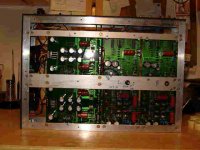
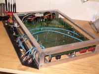
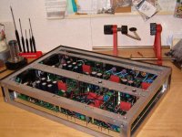
I finally have my ONO assembled. Built with pquadrat s boards.
Thank you Peter . Thank you Nelson .
Itook some voltage readings:
-VCC=31.2V
+VCC=30.4V
Q14 emitter=12V
Q24 emitter=25.5V
Q15 drain=15.5V
D5=31V . 29.3V
R67=1.08V
R53=1.08V
R28 Set at .35V
Both channels readings are extremely close.
I had a brief listen and it sounds good.
Iwill attempt to post photos.
What do you think guys?
Mike
Attachments
- Home
- Amplifiers
- Pass Labs
- Aleph Ono Project (from PCB group buy)