Hi guys....
Hope somebody in here has some hints to share.
I just finished my Aleph Ono clone today, and while one channel works flawless, I have a problem with the other. I´m able to adjust the 350mV operating point on both, although the faulty channel requires around 100 ohms more than the good one (measured on R25P). On the good channel, the voltage across R65-47ohm is around 600mV (the schematics says 420mV), so I guess this is ok. On the faulty channel the voltage across R65 is 7,6volt, it starts smoking, Q8 and Q19 gets extremely hot. I´ve checked for shortage, missoldering and similar but can´t find anything.
I sold most of my mesuring gear to my old job, got fired and now my only gadget is a digital multimeter.
Any help will be highly appreciated 🙂
Edit. The boards are the blue ones made by Nagard (just for info)
Last edited:
so , ask Nagard for help .........
or post enough info here , just to not have us guessing from the dark ..... regarding physical layout and exact schematic
or post enough info here , just to not have us guessing from the dark ..... regarding physical layout and exact schematic
I haven´t figured out how to upload pictures yet, sorry for that.
No need to be rude though. Just thought that a lot of people here know the Aleph One, have built the themselves, and might know. The schematics are the original Ono, so are the component values and designations. Why would the layout matter in this??
Why don´t you just stay out of the tread, if you´ve got nothing to offer???
In the 'Reply to Thread' window, scroll down to find the 'Manage Attachments' button.I haven´t figured out how to upload pictures yet, sorry for that.
Aleph 1 power amp or Aleph Ono preamp? And is that the X Ono or something different?Just thought that a lot of people here know the Aleph One, have built the themselves, and might know.
I don't think many people have the inclination (or time) to go searching for the information - schematic, layout, etc.. to answer your questions, unless you make it easy for them. People here are extremely helpful (some in their unique ways 🙂 ) but we need to do our parts as well.The schematics are the original Ono, so are the component values and designations. Why would the layout matter in this??
(Unless they have memorized the schematic and know what you are talking about when you refer to R25P or R65..🙂 ).
You can easily add links to the schematics, and other info using the 'Internet Link' button at the top of the reply window - between 'Increase indent' and 'Remove link'.
Thanks VG 🙂
I´ll try to sort it out.
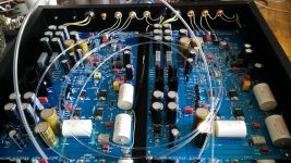
Seems to work 🙂..... Thanks. The fiberoptics were not finished in this picture.
They are glued to one LED each and then used as indicators in the black acryllic front panel.
I´ll find a better picture in a moment
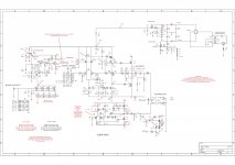
I don´t know, if it´s OK to upload the schematics.
If not, I hope an admin can remove it again.
I´ll try to sort it out.
Seems to work 🙂..... Thanks. The fiberoptics were not finished in this picture.
They are glued to one LED each and then used as indicators in the black acryllic front panel.
I´ll find a better picture in a moment
I don´t know, if it´s OK to upload the schematics.
If not, I hope an admin can remove it again.
Attachments
Last edited:
.......
Why don´t you just stay out of the tread, if you´ve got nothing to offer???
yup , why not ......
I'm in the process of finishing two Ono sets which have been sitting around half-finished for ten years ( for various reasons ). I too have some issues with odd voltages, but I left the boards at the lab at work. The voltages indicated on the schematic, - are those your voltages, or what they are supposed to be???
Hi AuroraB.
The voltages indicated on the schematic are what they´re supposed to be.
I´ve done some more measures, and ooops.....
The right channel (which I thought was OK) has issues too. On the junction R10/R27 right before the output cap, I have 16 volts instead of around 80mV. On all I´ve read about the Aleph Ono, I never read anything about matching the IRF´s. Could it be, that they are so different in specs, that this is the result, and maybe it would help to match Q7/Q18 and Q8/Q19 ???
Good to have a fellow diy´er with similar problems 🙂
Hope we get them sorted out.
I guess you know that LED D5 must have an Vf about approx. 1,6V?
Otherwise Q7,8,18,19 are getting hot cause the value about R25 is wrong.
The fiber optics for this position is not a good idea ...
Kind regards
Andreas
Otherwise Q7,8,18,19 are getting hot cause the value about R25 is wrong.
The fiber optics for this position is not a good idea ...
Kind regards
Andreas
Thanks for the info Andreas 🙂
I´ll measure the LED´s, and if wrong I´ll order new LED´s with specified voltage and move the fiber optics to the relay LED´s instead
I´ll measure the LED´s, and if wrong I´ll order new LED´s with specified voltage and move the fiber optics to the relay LED´s instead
Thought I might as well write this in public instead of a private message 🙂
A user made me aware in a PM, that since neither I or Zen Mod have English as our first language, maybe we (I) misunderstood each other in our previous posts. That may very well be so, and after reading my own answer, I must admit, that I´m not too proud of myself.
So therefore my deepest sincere apologies to Zen Mod for my way of answering his first post in this thread. Hope you can forgive me and we can get back on track😉.
Sincerely...... Boydk.
Last edited:
no big fuss
if you re-read my post , you'll realize that I wasn't rude ...... I simply gave you two logical options :
1.if someone is selling you some electronic goods , it's logical that you can expect at least minimal help from seller ...... especially if entire operation is based on communication through Forum
2. if No.1 is not feasible , we usually need all specific info to be able to help ...... too many times I've seen miscommunication , simply because one is talking about one part's nomenclature , while other one is talking about different one
As to point 1. :
I bought these boards just a couple of years ago from an elderly danish diy´er, who gave up on the project.
I wasn´t quite aware of what I was buing, and to search for help from seller would be No Go.
Later I discovered, that this was kind of an "old project".
But thanks Zen Mod.. for no hard feelings 🙂
I took Andreas´s advice, and ordered 10 LED´s of specifically 1.6volts.
In the same order was 10 pcs 610´s and 10 pcs 9610`s. Just to make best matches as possible.
If this doesn´t help I hope I can consult you guys again, but hopefully it does 🙂
Last edited:
Well....
It didn´t help in first try😡, but I was lucky enough to get hold of Dragan, who told me, that these blue boards (his first) had some production problems. They weren´t all etched properly, so I might have a short or two from a soldering point tor the overlay screen. With that info it took less than an hour to find both errors, and after fixing them, everythig fell into place, got adjusted properly and now work flawlessly. All operating points are without margins according to spec´s, and the sound.... OH what a sound🙂. My Sumiko Palo Santos has never ever sounded soooo good.
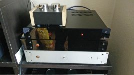
Picture of my shelf from bottoms and up:
My DIY DAC, the PSU for the riaa, the Aleph Ono Clone, and the DIY cabinet with 2 Silk Audio MC-220A SUT´s to top it.
Special thanks to AndrewT for the dual fet´s and an even bigger thanks to Papa PASS for "pass-ing" this great construction on to the DIY community.
For now this my absolutely final riaa😀😀
It didn´t help in first try😡, but I was lucky enough to get hold of Dragan, who told me, that these blue boards (his first) had some production problems. They weren´t all etched properly, so I might have a short or two from a soldering point tor the overlay screen. With that info it took less than an hour to find both errors, and after fixing them, everythig fell into place, got adjusted properly and now work flawlessly. All operating points are without margins according to spec´s, and the sound.... OH what a sound🙂. My Sumiko Palo Santos has never ever sounded soooo good.
Picture of my shelf from bottoms and up:
My DIY DAC, the PSU for the riaa, the Aleph Ono Clone, and the DIY cabinet with 2 Silk Audio MC-220A SUT´s to top it.
Special thanks to AndrewT for the dual fet´s and an even bigger thanks to Papa PASS for "pass-ing" this great construction on to the DIY community.
For now this my absolutely final riaa😀😀
Attachments
I got held up with other things, so I had to let the Ono project sit for a while. You say voltage values are within rating - is this based on the schematic you posted?? I have three different lists of values which differ somewhat. I also had problems with the LED voltage, but that can be solved......
Yes... It´s based on the schematic I posted. All values are fine, the offset before the output caps is even less of what the schematics show (around 20-25mV).
I couldn´t get LED´s with a forvard voltage of 1.6V, but had no problem getting some, that were specified to 1.65V. When soldered in, they measure exactly 1.66V which obviously is more than good enough.
The exact faults on my boards were: Board 1, basis of Q4 shorted to overlay ground, which resulted in Q8 & Q19 running extremely hot, 7-8 volts across R65 whitch got it to smoke pretty quickly. Board 2, positive pole of C1 shorted to overlay ground, causing an offset on the positive output before the output cap of around 16Vdc. Once these shorts were removed, everything was super.
Good luck with yours. Hope you get the errors sorted out🙂
Last edited:
- Status
- Not open for further replies.
- Home
- Amplifiers
- Pass Labs
- Aleph Ono Clone help