Come to think about it more, you only need a CL-60 on your primary red wires. CL-60 should not be used in series.
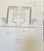
Rewired terminal blocks exactly per drawing below. Plugged it in and got same result. Neutral side fuse blew after a 5-6 seconds. Amp leds light; PSU leds don't on both sides.
ZenMod: Great idea on separate fuses. Given this situation. Need to double check switch capacity.
Thanks all. Next?
.jpg")
#3. above: see drawing. is this okay?1 - Did you wire the mains "hot" with the black wire and mains neutral with the white wire? Mains "hot" should go to your trans primary red wires, and the mains "neutral" to your trans primary black wire. "YES"
2 - Your yellow safety cap is perfect along with your CL-60's! "THANKS"
3 - Move your trans primaries so that both black wires are on the same phillips screw, the outer terminal strip with the Cl-60 in series and both red primary wires on the same phillips screw on the other outer terminal strip. Just flip one of your ring terminals upside down and mount the other ring terminal so it sits flat on top of the other ring terminal, you want them up and down, not side by side. The screw will tighten and stay tight that way.
ZenMod: Great idea on separate fuses. Given this situation. Need to double check switch capacity.
Thanks all. Next?
is this okay?
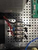
Here is a picture of the terminal block on my ALEPH J, the red wire is mains "hot" and the black wire is mains neutral. Notice the blue safety cap is connected to mains "hot" and mains "neutral".
I used a CL-60 from mains "hot" to each red primary winding wire. Nelson Pass recommends using just one CL-60 for both sets of primary windings.
Attachments
for start, when you decide how to wire primaries, and finally introduce dedicated fuse for each Donut, disconnect bridges (one wire leading to) so secondaries are without loadNext?
then see what's happening with power applied
if fuse OK, start connecting one by one thing to secondaries
first just bridge(s)
then cap bank(s)
then channel(s)
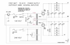
Here is the schematic for the ALEPH J power supply, it uses two CL-60's, one for each primary winding.
I built this amp in 2018, since then I've used the schematic for the F5 turbo power supply, which only uses the single CL-60 for both red primary windings.
I built this amp in 2018, since then I've used the schematic for the F5 turbo power supply, which only uses the single CL-60 for both red primary windings.
Attachments
I added labelling to the four wires on the left hand side. Please check that Red1 and Black1 are from the same primary. (And same with Red2 and Black2). You can confirm this by checking for continuity between Red and black wires. You want to make sure each primary has one thermister in series.
Attachments
Thanks for all of the replies. I unwired both the front panel switch and the IEC switch just to see if there was something odd going on with them. They were fine- still blew a fuse. Zen Mod, I disconnected all the transformer secondaries wires (my interpretation about what you were suggesting.) Still blew a fuse. My next trial will be to run each PSU separately. In my noobie mind, though, it seems like it's got to be before the transformers since the leds on both PSUs fail to light up and there just aren't that many other possibilities (in my noobie mind).
With regard to CL60s, I'm not hearing that as a problem for these symptom rather things that might be better practice. Is that correct?
With regard to CL60s, I'm not hearing that as a problem for these symptom rather things that might be better practice. Is that correct?
Dennis, thank you. I checked my wiring against your labels and it was correct. I checked the continuity of the primaries. They were correct. The fact that the amp worked very well without a hiccup for 7 months and then stopped working just seems odd. It was just sitting on it's shelf being turned on and off a couple of times a day and then one morning it wouldn't turn on.
Zen Mod, I'll put in separate fuses but that will take awhile since I don't have any fuse holders laying around. Is mentioned above I can still unwire one PSU at a time and see if that adds some info.
Zen Mod, I'll put in separate fuses but that will take awhile since I don't have any fuse holders laying around. Is mentioned above I can still unwire one PSU at a time and see if that adds some info.
Measure actual resistance vs. simple beep test. Different meters beep at different measurements.If I put one multimeter probe on either hot or common side AC inlet and the other end on any of terminal screws (plus or minus) I get continuity.
Either way, are you talking about one meter probe on common and other probe on your terminal blocks used to connect mains to your primaries? There's no (+) or (-) for that. OR are you saying that you have continuity from your mains common to the output of your DC supply? Something different? Sounds silly I know, but there can be a ton of miscommunication around measurements. When in doubt, tell exactly how meter was set and exactly where probes were placed.
It was working for some time, so I'm not sure why a rehash of all the mains/transformer wiring is needed or changing to different inrush style. It can't hurt, but it likely wasn't root cause. I'm not saying that it's not important... just that if it was working properly before, then all you're doing is tidying up. Find most likely root cause... then you can tweak if you want.At any rate, there must be an incredibly simple answer as to why this isn't working. Ideas?
For everything below make SURE you pause for at least a minute between turning the power off and powering back on. The thermistors need time to cool.
What I'd do if I were you is:
Make sure fuses are slow blow.
Disconnect both amp boards. You've got Euroblocks, so it should take less than 5 mins.
Check each PSU to see if you have proper DC output and don't blow a fuse. Note results.
If OK move on. If not, report.
Add amp board #1. See if fuse goes pop. Note result.
Disconnect Amp board #1
Add amp board #2. See if fuse goes pop. Note result.
If both amp boards successfully power back up, you may be right on borderline of 3A fuse... bump to next value up.
Maybe some wonky wiring shifted.
If none of that provides clues... only cost 20 minutes tops, and you likely won't cause any damage.
Thanks AllInMyHead. I'm not using slow blow fuses, just regular 3 amp fuses. Could that be the whole thing? It's certainly could explain the symptoms. Just ordering slow blows.
I'll go through and note resistances from AC common to each terminal block screw, That wasn't what I was checking before.
I'll go through and note resistances from AC common to each terminal block screw, That wasn't what I was checking before.
Yes, it could.Could that be the whole thing?
Edited - Sorry... Accidentally posted an incomplete message.
There still are a number of things to check... but first... put in slow blow fuses.
Don't worry about the resistance checks.
Just begin with step right after installing the slow-blow fuses... at least that's what I'd do to narrow things down.
The inrush current even with the current (HA!) parts in place is going to be over 3A for a short while. Using proper slow-blow fuses is the first step, IMO... it may not be the last, but it could be...
Last edited:

New Update.
I fused each channel separately. I got slow blow fuses. I have made sure my wiring exactly corresponds to the drawing below with the exception that I've added a front panel switch. In the drawing below I've indicated how I wired it, I have not yet turned on the power because when I use a VOM to continuity check there is continuity between everything. For instance there is continuity between the two channel fuses output tabs; their is continuity between the channel fuse output tab on one side to each of the 16 screw terminals on the two terminal blocks. Likewise for the other side fuse. I got this same result before I did anything after it stopped working. Can this possibly be OK? If not, I cannot figure out where things got crossed. Is there a chance that a bad CL60 could be the culprit? Maybe it's supposed to be like this? Doubtful.


I fused each channel separately. I got slow blow fuses. I have made sure my wiring exactly corresponds to the drawing below with the exception that I've added a front panel switch. In the drawing below I've indicated how I wired it, I have not yet turned on the power because when I use a VOM to continuity check there is continuity between everything. For instance there is continuity between the two channel fuses output tabs; their is continuity between the channel fuse output tab on one side to each of the 16 screw terminals on the two terminal blocks. Likewise for the other side fuse. I got this same result before I did anything after it stopped working. Can this possibly be OK? If not, I cannot figure out where things got crossed. Is there a chance that a bad CL60 could be the culprit? Maybe it's supposed to be like this? Doubtful.
Well, if you're going to measure resistance... measure resistance vs. continuity as I previously recommended... and then told you to ignore. 🙂.For instance there is continuity between the two channel fuses output tabs; their is continuity between the channel fuse output tab on one side to each of the 16 screw terminals on the two terminal blocks.
Continuity beeps at what resistance for your meter? ... 🙂
Or a perfectly functioning one......Is there a chance that a bad CL60 could be the culprit? Maybe it's supposed to be like this? Doubtful.
What's the "cold resistance" of a CL-60...
Edited to add - We're not done yet... we'll check the front panel switch in a bit... was that added between when it worked and didn't?
Transformer primaries are long pieces of wire… there will be continuity between L and N if the transformer is attached.
Do you have continuity between either L or N to chassis ground? Check with the front panel switch on, also.
Looking at the picture in post #32 the two fuses are not visible. I assume that they are located toward the top of the back panel, and the red and yellow wires are the Live AC from the two fuses.
The AC wired from the IEC and fuses are not grouped in an orderly way, which makes it difficult to figure out the wiring, and also is not conducive to low noise.
The wiring can be improved by taking one pair of L and N wires from the IEC to one fuse and a second pair from the IEC to the other fuse. Tightly twist each pair of L and N to each fuse. Cut the L wire and connect to the fuse. Continue the L and N twisted tightly to the connection block at the front of the chassis.
The chassis ground is currently connected near the front of the chassis. This results in long runs of ground from the IEC and both power supplies to the front of the chassis. It would be better if the chassis ground and the PS ground lifts are located at the back of the chassis. This would result in shorter ground wires, and only the transformer shield wires need to be long. The bridge rectifiers can then be moved closer to the front and centre and the PS boards can be moved closer to the front to make room for the chassis ground and PS ground lifts at the back of the chassis.
Notice there was no question mark in my post .... Let them look it up 🙂 My nudge has been to help learn that "continuity" doesn't mean 0 Ohms / does not mean unintentional "short".Cold resistance of a CL-60 is 10 Ohms.
Transformer primaries are long pieces of wire… there will be continuity between L and N if the transformer is attached.
Exactly... but again... if they switch their meter from "beep test" to measuring actual resistance as I suggested... they might learn that... they can measure the actual resistance depending on their meter and see that it's likely just fine. 🙂
@getgoin - I generally prefer continuity to be interchanged with "not a really high resistance" instead of what I commonly think people use it for... which is "0 Ohms resistance". I was intentionally a bit cagey in an effort to lead you toward your answer. Stepping away. Good luck!
To give an example of what IAIMH is referring to, a member on the IronPre thread thought his transformer might have beem bad when he didn't get a beep on his meter. It turned out the measured resistance was sufficiently high (~60 ohms) to not trigger the meter's continuity circuit. So it's a good idea to double check the actual resistance value.
^ Good morning, Dennis - 🙂
Valid example, and 100% correct.
Specifically though in this situation.... slightly inverted...
The cautious user hypothesizes that there could be a "really bad issue" b/c their live and neutral mains wiring (putting words into their mouth) have 0 ohms resistance to 16 different measured points. If that was true, then I'd agree. I do not think that is true.
I had asked earlier (still no answer) what the threshold resistance for the "beeeeep" on their meter was...
When taking into account the thermistors... the proper wiring of the transformer primaries... etc... my guess was / and is... that their meter beeps b/c IMO they are measuring it the wrong way (using a less than ideal method) ... and assuming a beep means something that it does not along with not understanding the (relatively) low resistance of the thermistors and the primary wiring.
tl;dr - you provided an excellent example of the meter not beeping and misinterpreting .. vs. the meter beeping and misinterpreting.
Also... what happened to the "spark suppression caps"?
Last edited:
- Home
- Amplifiers
- Pass Labs
- Aleph J