Hi guys, my Aleph J started to hum so friend send he'd take a look. He replaced all the caps but now we have DC and AC at the speakers. What is the problem?Thanks,Chet
Check the caps for correct polarity where required.
See this thread regarding seting the bias and offset. You might need to figure out which pot is the bias and which is the offset according to your schematic. See post #3.
http://www.diyaudio.com/forums/pass-labs/241729-aleph-j-illustrated-build-guide.html
See this thread regarding seting the bias and offset. You might need to figure out which pot is the bias and which is the offset according to your schematic. See post #3.
http://www.diyaudio.com/forums/pass-labs/241729-aleph-j-illustrated-build-guide.html
We need more details. How much AC & DC is present? Is it mv or V? Is the voltage the same for each channel or does it affect one channel only? What were these voltages before your friend began the repair work? As VDI already pointed out, good pictures of the amps internals would help greatly.
It is not clear - is this a DIY Aleph J?
If it's actual FW product, then the owner should contact me for service.
That aside, is it doing this on both channels?
😎
If it's actual FW product, then the owner should contact me for service.
That aside, is it doing this on both channels?
😎
Hi Guys,
Glad to meet you all. I'm the friend who's looking into it. It's a DIY Aleph J. Test Rig setup is an IsoVariac, multimeter, scope and 4/8 ohm dummy resistor with bnc bung. At first glance, it had puffy filter caps (4 of 6 22mF 25V), two manilla circuit boards, and heat stress around the power mosfets.
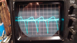
The sextet of filter caps were replaced, and the .47 ohm wire wound resistors across the caps read okay. I put some power to it, 20-30VAC, and tested that the bridge rectifier is functioning. An inline current meter shows 1-2amps draw before reaching 60VAC. At this point, the voltage was backed off, and the screenshot of the amplifier output was taken. On a separate test, I used a multimeter to measure about 400mA of DC output on each side, still at less than working voltage. Both sides do show a lot of DC, but the scope test may have only been tested on one side.
Thanks for your help. I could use more live-circuit testing experience, synthesis of related problems into an understanding of cause, and analysis of the data and visual feedback gathered from testing.
Since this is my first post, I'd like to mention that I'm a third year practicing DIY Tube Amp tech, working his way through a Self-Educated Electrical Engineering curriculum. I use some MIT Open Course Ware material, as well as view online forums such as this one, and read as much technical literature as possible. Biggest bane? Perhaps the lack of in-person experience with those who know better, and teach quicker. I sure love the scene enough to stick around and witness progression. You guys are awesome.
Rich
Glad to meet you all. I'm the friend who's looking into it. It's a DIY Aleph J. Test Rig setup is an IsoVariac, multimeter, scope and 4/8 ohm dummy resistor with bnc bung. At first glance, it had puffy filter caps (4 of 6 22mF 25V), two manilla circuit boards, and heat stress around the power mosfets.
The sextet of filter caps were replaced, and the .47 ohm wire wound resistors across the caps read okay. I put some power to it, 20-30VAC, and tested that the bridge rectifier is functioning. An inline current meter shows 1-2amps draw before reaching 60VAC. At this point, the voltage was backed off, and the screenshot of the amplifier output was taken. On a separate test, I used a multimeter to measure about 400mA of DC output on each side, still at less than working voltage. Both sides do show a lot of DC, but the scope test may have only been tested on one side.
Thanks for your help. I could use more live-circuit testing experience, synthesis of related problems into an understanding of cause, and analysis of the data and visual feedback gathered from testing.
Since this is my first post, I'd like to mention that I'm a third year practicing DIY Tube Amp tech, working his way through a Self-Educated Electrical Engineering curriculum. I use some MIT Open Course Ware material, as well as view online forums such as this one, and read as much technical literature as possible. Biggest bane? Perhaps the lack of in-person experience with those who know better, and teach quicker. I sure love the scene enough to stick around and witness progression. You guys are awesome.
Rich
Okay, here are some photos... and a little data.
All tests @ 30VAC
AC at the speaker terminals = .75-1.5V (and climbing)
DC offset = 400/470mV, channels 1/2 ( seemed steady, but shot to over 1V after a few minutes)
The top pair of mosfets read 9V, 9.5V, and 5V, from left to right as you view them in the picture. The bottom set, if you were to look at them in their upright (corrected) stance would read 4V, 5V, .1V DC.
Same for the other channel. Did something cook the bias circuit on both boards as a result of the failing filter capacitors? It's funny, I am also working on a tube amp with a shorted Output Transformer, and a related destruction of the bias circuit. The correct bias was brought back to the amp when the burnt power resistor and the bad electrolytics were replaced. Still needs a new OT.
no pictures
remember that Aleph CCS demands at least 10V-ish across it to became functional , so - you can use variac as safety measure having an eye on current meter , but you cant expect any sane behavior of circuit at less than optimal voltage
so , I believe what you are seeing is pumping of Aleph CCS while input LTP is still not able to maintain its servo function , while rails are lower than needed
put 3A15 fuses in rails in between PSU and channel pcb and bang it
though - it's still best to post pictures , before proceeding .....


Wow Zen Mod, you were absolutely right. After getting right to it, the scope noise disappeared at about 55VAC. 1.9A held steady up to full line voltage.
Then, I had a day to listen to it, and 😉 make sure it sounded good. HA! I'm happy. Sorry guys, a million words won't cut it. There's a new Solid State tinkerer on the loose.
Then, I had a day to listen to it, and 😉 make sure it sounded good. HA! I'm happy. Sorry guys, a million words won't cut it. There's a new Solid State tinkerer on the loose.
Wow Zen Mod, you were absolutely right. .....
pretty normal , at least for 50% of cases

enjoy .......
Really looks like one of Rawson's abominations. Maybe it's this one? FS: Aleph J clone ***SOLD*** Total piece of crap.
Really looks like one of Rawson's abominations. Maybe it's this one? FS: Aleph J clone ***SOLD*** Total piece of crap.
That is actually a "Rawson" signature edition, check out the back panel in those pictures.
When someone dies from the lack of a proper chassis ground on one of his amps I can see the prosecuting attorney using the back plate of the amplifier as evidence against him. Can you imagine the look on the builders face when they parade the back plate from his death trap amplifier in front of the jury.
BTW there are two of Rawson's builds on Audiogon right now and one of them shows a picture of the internals. Looks like it too is lacking a proper chassis ground. I can understand maybe not including the CL60 as a ground loop break, but completely ignoring the mains chassis ground is hard to fathom. Even though Mr. Pass's schematics show these connections it appears the builder was either too lazy or too lacking in knowledge to include this ground, maybe the answer is both.... How his amps have managed to capture the audience they have is really amazing.
TankAudio do your friend and any future owner of this amplifier a favor and add the proper AC mains ground circuit that ZM is speaking of.
Ah yes. Plenty of reason there. That is the "exact" amp before I replaced the caps. They were Nichicon LQ series.
The chassis work could be better. The grounding correction will proceed.
Of mention, I'm not completely out of the woods. A small sonic issue (from the perspective of the listener)?
Inside the chassis, The black and grey mains wires cause a hum when in certain positions, or perhaps when they are too close together. The noise almost resembles a quiet, low frequency sizzle, that appears to originate from within the transformer. It is not very loud, but has the feeling of being mechanical in nature. When the leads are separated, using two wooden clothes-pins at the position where the PT leads are soldered to the black and grey wires (specifically near the heat shrink) the issue is subdued. The heat shrink quality is unknown.
The amp stays running as expected, regardless. The noise comes on like an ON/OFF switch, rather than a volume pot being turned up and down.
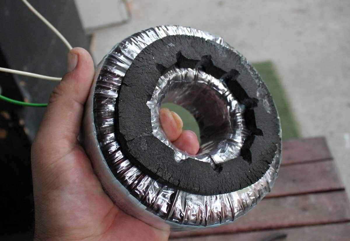
fiddle with xformer screw and proper cushioning
example
Babelfish J2 , pair of them , for Denmark ……. (Blast from the Past) | Zen Mod Blog
example
Babelfish J2 , pair of them , for Denmark ……. (Blast from the Past) | Zen Mod Blog
- Status
- Not open for further replies.
- Home
- Amplifiers
- Pass Labs
- Aleph J