Hi Guys, I finally got to powering up the first of my Aleph J boards this morning.
DC Offset 20V - I thought, "Oh my God !!"
However, I can adjust the offset down to zero and set the Iq to about 585mV across R16.
My question is, if I leave it for a few minutes the DC offset is back to +/-20V.
I can adjust it again back down to almost zero but it is just not stable.
DC Offset 20V - I thought, "Oh my God !!"
However, I can adjust the offset down to zero and set the Iq to about 585mV across R16.
My question is, if I leave it for a few minutes the DC offset is back to +/-20V.
I can adjust it again back down to almost zero but it is just not stable.

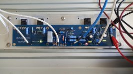
ref. schematic and less fuzzy, closer pic
boyz having intimate knowledge of these pcbs need to chime in to check did you chose proper solutions, regarding several optional positions
or you can detail them here
edit: is the same with both channels?
boyz having intimate knowledge of these pcbs need to chime in to check did you chose proper solutions, regarding several optional positions
or you can detail them here
edit: is the same with both channels?
R27 seems to only be able to achieve 580mV across R16 at max. It can adjust the Iq down from this value but not up to 600mV.
I think R27 requires a jumper, but someone more experienced should chime in to confirm / refute before any action.
Much more clear. Offset on Aleph J should only be around .400 mV, why are you trying for 600 mV?
Russellc
Russellc

Post #1 on 6L6 build guide
Let's talk about this - as it is somewhat confusing.
There are 3 places for R27 on this PCB. The first is the pad next to the cap C2. (in the above photo it is empty) I suggest making that one a jumper.
Where the jumper is placed in the photo should be open, and under the green insulation you will find the place for a pot.
SO - place a 100K pot where the pot will fit and jumper the vertical 'R27'. Set the pot to 68K before you turn the amp on the first time.
Scroll down to you see the pics concerning R27 and jumpers.
Russellc
I'm going to replace R27 pot with a 25T pot, I'm only using 10T which may be the problem.
do whatever you want..... but it could be useful if you read and actually reply on questions

- Home
- Amplifiers
- Pass Labs
- Aleph J Setting DC Offset