Look on the fourm about ACS explanation. Altering R27 changes the the acs gain/modulation and with it, contribution of upper fet to output. Nelson decided on his values for a reason and I would imagine it is better overall performance. I have read that performance at 1w can be improved slightly, but at the expense of performance at higher power levels.
in the future I wish to listen to the amp without R27(pure class a) in the circuit but the bias on my side is already high(1.6A/fet and 60C on the sink measured last summer) and I don`t want to get everything on fire 🙂
How high the bias/fet gets in the original circuit without R27?
How high the bias/fet gets in the original circuit without R27?
THE bias of the current source is .65V divided by the Rs of the top fet. If you cut modulation component, then you have a SE amp driving a CCS load. With 1.6a, you better have beefy sinks. The original was bout 1.2A(.66/.47)
ups 🙂 i did it again
for pure class a I have to remove R24
I remember now that i read somewhere here that also without R27 the sound gets better
confused you a little bit..sorry
for pure class a I have to remove R24
I remember now that i read somewhere here that also without R27 the sound gets better
confused you a little bit..sorry
Last edited:
Here is basic schematic. If you want to have just SE amp with CS, you dont need R24, r27, r20-23, and c3. These are the componenents that turn it into a modulated current source, where the signal affects the response of the current source and its contribution to the output.
Attachments
so the trick it`s that I have to remove all those components to achieve pure class a, not only R24...ok now I get it
you cleared a little bit the things for me, thank you!
you cleared a little bit the things for me, thank you!
Look at Zen V2 article on Firstwatt site. The second part of the article he sets up a SE amp with a CCS load. He follows that article up with ZV4, where he introduces the ACS. THe AJ just adds a LTP too the front end and creates nice feedback point as well as ability to drive with balanced signal.
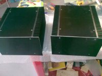
A journey started a long time ago...🙄
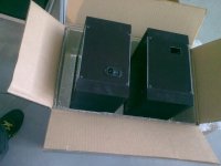
hope to finish it soon
Happy New Year to all!!

Happy New Year !!!
Looks nice !!

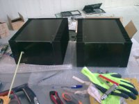
tomorrow I want to drill some venting holes in the top and bottom pannels but I have a little problem...as always 🙂)
does the size of the holes matter? I thought at 2 options
- single row of holes with relative big hole diameter(10mm will suffice ?)
- 2-3 rows of holes with 3-4mm hole diameter
in which of the cases the convection would act at maximum?
the first row of holes will be at 20mm distance from the heatsink
I would choose the larger holes. Less drilling required, and (my opinion) better aesthetics.
And you can make adjustments not taking off the hood 🙂
I think he means that you may be able to get an adjustment screwdriver on the adjustment pots (if you include any) through the ventilation holes.
yes...so the kids would adjust it when i`m not at home 🙂
hard decision.. will wait few days so all the components arrive and I`ll see after
thanks for the tips
hard decision.. will wait few days so all the components arrive and I`ll see after
thanks for the tips
My kids have gotten used to open amps laying around. It causes them to ask questions like ,what is electricity. I love it. Amps are looking great. 6L6 is resident perfectionist. Check out his awesome build threads.
- Home
- Amplifiers
- Pass Labs
- Aleph J Schematic