EUVL said:> .........
A better one would be one without any additional -ve supply.
That is now the challenge.
😀
Patrick
if we use slightly higher rails - is it cheating?
and - rail to rail is must?

> if we use slightly higher rails - is it cheating?
No. But that gets you back to post#241 which is really equivalent to the first solution in post#220..
I have the feeling that you are really going round in circles right now.
Patrick
No. But that gets you back to post#241 which is really equivalent to the first solution in post#220..
I have the feeling that you are really going round in circles right now.
Patrick
EUVL said:> if we use slightly higher rails - is it cheating?
No. But that gets you back to post#241 which is really equivalent to the first solution in post#220..
I have the feeling that you are really going round in circles right now.
Patrick
hehehe ........ then teach me ....... 😉
there it is - another perpetuum mobile from ZM's cousine
EDIT:
have you measured data for LU xconductance?
Attachments

The J511 on the RHS somehow stops the diff pair from working ??
And splitting the 1k into 250 does nothing but reduce 1st stage gain by a factor of 4. In fact, the 750R might as well be removed.
> have you measured data for LU xconductance?
You can calculate from the slope of Id vs Vgs.
Under ZV9 bias, it is about 4S, and the source resistor is dominant.
Patrick
EUVL said:The J511 on the RHS somehow stops the diff pair from working ??
And splitting the 1k into 250 does nothing but reduce 1st stage gain by a factor of 4. In fact, the 750R might as well be removed.
> have you measured data for LU xconductance?
You can calculate from the slope of Id vs Vgs.
Under ZV9 bias, it is about 4S, and the source resistor is dominant.
Patrick
so looking at difference between LU and , say, IRFP150 - it's >cunning< to increase drain res for same ratio .......
naah ...... maybe I'll just use nice choke under that 2SJ

EDIT _ I know that that J511 can't work like that ........ I told ya that is Perpetuum Mobile
Attachments
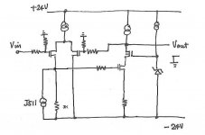
> naah ...... maybe I'll just use nice choke under that 2SJ
Good. You get 0V across at DC, right.
BUT, now you need a choke that has a constant impedance from 20Hz to 200kHz, or you have frequency dependent open loop gain. AND 90° phase shift ??
😉
Patrick
Good. You get 0V across at DC, right.
BUT, now you need a choke that has a constant impedance from 20Hz to 200kHz, or you have frequency dependent open loop gain. AND 90° phase shift ??
😉
Patrick
Anyone thought about using P-channel MOSFET for cascode of output JFET? That would put the MOSFET between the JFET and -ve supply.
Metalman adds to confusion
Metalman adds to confusion
> Metalman adds to confusion
Yes.
Please re-read ZV9.
The IRFP240 cascode device source is NOT at constant voltage during swing.
Patrick
Yes.
Please re-read ZV9.
The IRFP240 cascode device source is NOT at constant voltage during swing.
Patrick
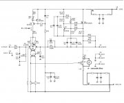
Nelson Pass said:I haven't finished the service manual for publication, but it is
quite clear that many have become impatient.
www.passlabs.com/np/Aleph_J_sch.pdf
😎
From Nelson's schematic above, I believe there should be a 221k resistor to ground after -input resistor R3. Mr. Pass?...
Re: Re: Aleph J Schematic
No, that is provided by the 221K feedback resistor.
😎
Blues said:From Nelson's schematic above, I believe there should be a 221k resistor to ground after -input resistor R3. Mr. Pass?...
No, that is provided by the 221K feedback resistor.
😎
some referring material
referring to http://www.ne.jp/asahi/evo/amp/SITamp.htm,
maybe some new ideas come out, i think .
Zen Mod said:
so looking at difference between LU and , say, IRFP150 - it's >cunning< to increase drain res for same ratio .......
naah ...... maybe I'll just use nice choke under that 2SJ
EDIT _ I know that that J511 can't work like that ........ I told ya that is Perpetuum Mobile
EUVL said:> naah ...... maybe I'll just use nice choke under that 2SJ
Good. You get 0V across at DC, right.
BUT, now you need a choke that has a constant impedance from 20Hz to 200kHz, or you have frequency dependent open loop gain. AND 90� phase shift ??
😉
Patrick
referring to http://www.ne.jp/asahi/evo/amp/SITamp.htm,
maybe some new ideas come out, i think .
> referring to http://www.ne.jp/asahi/evo/amp/SITamp.htm
They all run an additional -ve supply, and we have already discussed that.
Patrick
They all run an additional -ve supply, and we have already discussed that.
Patrick
Why not wait for NP's PCB layout?
I'm sure I'm missing something here, but since Mr. Pass will, if past is prologue, eventually publish his own PCB layouts, why spend so much time and energy on interpreting the schematic? I for one would be more than happy with a diy clone of the Aleph J, using the master's own board design.
Are the variations here meant to improve on performance or reduce cost? Seems to me the biggest ticket items will be the toroidal transformer and the chassis, which you will need regardless.
Or is it just the pleasure of the intellectual pursuit, like taking one of Miles' charts and blowing your own riffs on top of it? If I understood amplifier design better than I do, I could appreciate that.
I don't mean this as flame bait, not at all. I built various kits back in the golden age, the 60's, and have recently built a diytube clone of the classic Dyna ST-35 that I'm really happy with. And I purchased brand new a Threshold 400A circa 1979 that I loved a lot. I'm really intrigued with the idea of building one of Nelson's designs.
I just get a little blown away by some of the discussions here, and a little intimidated.
Thanks,
Larry
Re: Why not wait for NP's PCB layout?
without offense, but - yes .
lafish said:I'm sure I'm missing something here,................
without offense, but - yes .
Hi Larry,
don´t waste any more time!
On www.analogforum.de is a tread where a layout based on Papas´ schematic has been made.
It is not like the original layout, but an adaption for better practicability.
As the original Aleph J is available to a member in the forum, they also stand the chance of a real A-B comparison.
Btw, they have a deadline ending today for pcb orders...
Cheers
Zen Mod said:
is this cheating?
I think that this schmtc is good enough for start ; without Aleph CCS for start ( without CCS modulation) , just twidling with few parameters ; it's easy to implement right amount of modulation for upper half .....later
edit:
I forgot to say that PSU filtration is premised to be good ......... anyway 😉 , same as for any A class amp

Choky,
I am a bit tied up this week. Maybe earliest next week before I have time to look in detail.
Why not do some simulations of the 3 main proposals in the meantime (J511, 4V Zener below LU1014 source resistor, and yours) ?
🙂
Patrick
I am a bit tied up this week. Maybe earliest next week before I have time to look in detail.
Why not do some simulations of the 3 main proposals in the meantime (J511, 4V Zener below LU1014 source resistor, and yours) ?
🙂
Patrick
- Home
- Amplifiers
- Pass Labs
- Aleph J Schematic