I am used to use holes whenever I can, hence increasing amount of family duties due to ever increasing amount of mini berserkers.
Mighty, you saying not to use holes even though they are there, or just not to bend? I wasn’t going to bend the contact plate, just put in the wire, ensure it is vertical (hence «bend»), then solder. Papa uses the holes in FW builds, so kinda figured a good idea. I might be a GH but not a complete *** ok, then, maybe a bit.
But I figure using holes is an easy way of ensuring mechanical contact.
My assumption is on a FW or other commercial amp the assumption is it will likely NEVER be touched again, and doing the most simple, most reliable, highest integrity connection would be the default choice. If there is a fault, no big deal for the service center to unsolder and resolder a few connections to pull a part.
I think I am seeing a lot of people using connectors that can be disconnected so they can pull out parts without having to desolder and resolder.
Andy, thanks for your comment. I will play it by ear, but I think I will try to find a balance between soldering and connectors - with the goal being if I need to remove one of the three boards I don't have to unsolder a ton of stuff.
On my ACA where it was pretty much 'done' when done, all solder makes sense there. On this build might try to have a few places to unplug - off the top of my head the connections on the power supply board to the amp boards might be nice to unplug. Again need to actually start playing with it.
BTW, my chassis has been sitting in Paris for a week waiting for a plane, oh well, not in a rush!
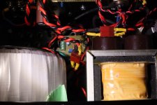
A compromise would be putting connectors in the wires instead of at the board. I have done that with some of my amps.
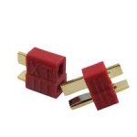
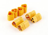
Pictured is an amp where I put couplers in the V+/Ground and speaker out. The amplifier only requires V+ and Ground so I used Deans connectors, which are two conductor connectors. These connectors a commonly used in RC batteries. For three conductors, as required for V+, V-, and Ground, there are MT60 couplers.
Pictured is an amp where I put couplers in the V+/Ground and speaker out. The amplifier only requires V+ and Ground so I used Deans connectors, which are two conductor connectors. These connectors a commonly used in RC batteries. For three conductors, as required for V+, V-, and Ground, there are MT60 couplers.
Attachments
messing with holes on bridges is just feeding the OCD
as always, do what make you happy .....
And filing the plated connectors is Zen?

I really need to figure out the balance between OCD and Zen. Maybe feeding Zen feeds OCD? And perhaps, OCD sometimes feeds some Zen iot enjoy the muzak in peace?
Many good tips and creative and practical ways came out of this. Thank you ZM, Boky and Ben Mah!
I am thinking, using a P2P PSU, I won’t be disconnecting bridges very often. And power wires will have to be screw connected to the PSU anyways. That leaves only a need for quick connects on signal and speakers wires. And I want those soldered anyways. Will ponder a bit more, but think I in this build will solder most of the connections, apart from the PSU which will need correct torque and maybe some tac.
Plus, using a big tip and powerful station, unsoldering is not so bad.
«Happy DIY - striking the balance between Zen and OCD».
Regards,
Andy
A compromise would be putting connectors in the wires instead of at the board. I have done that with some of my amps.
Pictured is an amp where I put couplers in the V+/Ground and speaker out. The amplifier only requires V+ and Ground so I used Deans connectors, which are two conductor connectors. These connectors a commonly used in RC batteries. For three conductors, as required for V+, V-, and Ground, there are MT60 couplers.
now, that's clever

A compromise would be putting connectors in the wires instead of at the board. I have done that with some of my amps.
Pictured is an amp where I put couplers in the V+/Ground and speaker out. The amplifier only requires V+ and Ground so I used Deans connectors, which are two conductor connectors. These connectors a commonly used in RC batteries. For three conductors, as required for V+, V-, and Ground, there are MT60 couplers.
Ohhh, very interesting. I like that. Thanks for sharing.
Can you help with what fuse I should use? I see three options (2.5, 3, 4 amps)
--In the FW Aleph J owners manual I see 4 amps: '3AG slow blow, 4 A (120VAC)'
--In the Blogspot build guide he references a 3 amp fuse (for 120V)
--On Page 1 of this thread under 'Power Supply' I see the schematic referencing a '2.5A' fuse
Also, while it is coming back I noticed the Ametherm part suggested is on backorder. If this is the exact, precise part I need, I can wait. However, I will actually be in Reno, NV (tomorrow) and might see if they happen to have any to sell me in person 🙂
MS22 20005 Ametherm | Mouser
Thanks!
declared VA of xformer/mains voltage
choose first closest standard value, down or up, increase if it pops often
choose first closest standard value, down or up, increase if it pops often
Thanks!
I ordered the 400VA AnTek, and my real wall voltage is 120V (rarely changes). If my exhaustive math is correct, that gives me 3.33A
Unless anyone suggests otherwise, I would very much like to round DOWN to 3A or 3.15A. Anyone have a favorite flavor (a specific brand, series) that they think works best? Anything in-stock at Mouser is OK!
Thanks TungstenAudio - will the one you just linked limit current more or less than the original one (MS15 40004)? I see the one you linked is 20 vs. 40 ohms (which would be more restrictive?)...but the current is also higher (5 vs 4.1 A...if I would ever reach that max limit). Not sure if those interact with each other.
It’s not that simple. The initial resistance is higher, but the final resistance will be close. That’s due to the lower amp rating. Try it. Should be just fine. The other parts will be available next month.
Thanks. I’ll trust you know!
Any thoughts on fuss or any standard 3A or 3.15 ok? Slow blow 250v
Any thoughts on fuss or any standard 3A or 3.15 ok? Slow blow 250v
Hi, am in the process of building the Aleph J and some help and opinion will be appreciated.
I have two power supplies and don't know which one to choose?
1x 600VA 2x18V = 1x 8x47000uF
or dual mono:
2x 300VA 2x17V = 2x 8x22000uF
Will be there any practical difference in power output between 17V and 18V transformer? Or will be more benefits in dual mono construction?
I have two power supplies and don't know which one to choose?
1x 600VA 2x18V = 1x 8x47000uF
or dual mono:
2x 300VA 2x17V = 2x 8x22000uF
Will be there any practical difference in power output between 17V and 18V transformer? Or will be more benefits in dual mono construction?
For what it's worth, one of the 300VA PSU will be sufficient for the entire stereo amplifier.
The difference of one volt will be a measurable difference in power, but not anything you could ever hear.
Dual mono is the better of the two choices, to keep the channels (and their grounds) separate.
Incredibly oversized transformers do not increase power in any meaningful way.
The difference of one volt will be a measurable difference in power, but not anything you could ever hear.
Dual mono is the better of the two choices, to keep the channels (and their grounds) separate.
Incredibly oversized transformers do not increase power in any meaningful way.
Surprise letter from Batsch arrived today. Ancient Batsch shields and swords from the previously unknown Batsch-Viking wars, not unlike the Clone Wars. And NTC boards and some nicely traced PSU boards. Big hug to Mighty! Next time I’ll send you that revently discovered Viking ship:
Norway excavates a Viking longship fit for a king - BBC News
Norway excavates a Viking longship fit for a king - BBC News
Just finished my Aleph J build. Fantastic sounding amplifier. Thank you guys for all the great information. First try was a success.
Last edited:
Same noise, different day
Back in post #6861, I discussed my issues with some noise in the right channel of my Aleph J.
Per everyone's recommendations, I opened it up and checked every solder joint on the affected channel and on the power supply with a chopstick, and didn't hear the noise at all. I did notice the bias and DC offset on that channel needed a few small tweaks (the left channel remained pretty close to perfect). I set the bias and the offset, measured everything again, and put it back in the chain. No noise for about a month.
Then the noise again. Repeated the whole process. This time bias and offset had not moved. Chop-sticked every solder joint again and no noise. Made final measurements, and closed it up. This time, I got about 2 months of perfect sound with no noise.
Now I hear it again. Any other suggestions as to what it might be? Go back and check my post listed above for details and to listen to a sample of the noise.
Thanks for any advice you can provide.
Brad
- Home
- Amplifiers
- Pass Labs
- Aleph J illustrated build guide