@darrr
Thanks. Voltages measured from rail to ground, at the boards:
(+) 22.6V
(-) 22.7V
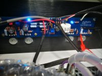
Pics might prove useful, I agree. I had a similar noise/offset issue with my first WLS build. Turned out - i think - to be one of the JFETs in the CCS, more specifically, i believe, a scratch in the PCB under the little JFET that apparently was in contact with one or more of the solder pads through flux and or the transistor body. Well, never quite managed to 100% pin the problem to that, but lifted a pad in the process and had to start over.. well well. You can hear I am no expert. Bottom line: sounds to me like one of your active components may be acting up somehow. Maybe some measurements of the same FE posistions Dennis Hui asked for a few pages earlier can shed some light on the issue, with help of pics. And can you (re)confirm both CCS MOSFETs are matched and have similar voltage drops over their source resistors?
Last edited:
Pics might prove useful, I agree. I had a similar noise/offset issue with my first WLS build. Turned out - i think - to be one of the JFETs in the CCS, more specifically, i believe, a scratch in the PCB under the little JFET that apparently was in contact with one or more of the solder pads through flux and or the transistor body. Well, never quite managed to 100% pin the problem to that, but lifted a pad in the process and had to start over.. well well. You can hear I am no expert. Bottom line: sounds to me like one of your active components may be acting up somehow. Maybe some measurements of the same FE posistions Dennis Hui asked for a few pages earlier can shed some light on the issue, with help of pics. And can you (re)confirm both CCS MOSFETs are matched and have similar voltage drops over their source resistors?
Will sure do check against the noiseless board, thanks for the tip.
I'll report back as soon as I get some time!
Hi, I carried out the first test on a channel of the Aleph J, to have acceptable temperatures, heatsinks around 60 ° C and Mosfets around 40 ° C, I cannot exceed 400mV for the BIAS current, with an OFFSET lower than 3 mV.
I tried to set the current of BIAS 450 mV but the temperatures are too high.
Is 400mV an acceptable value for BIAS current?
Thanks for the replies.
I tried to set the current of BIAS 450 mV but the temperatures are too high.
Is 400mV an acceptable value for BIAS current?
Thanks for the replies.
mosfets 60C , heatsink 40C ?
400mV across 0R47 gives 0.85A, which means you have twice that - 1.7A for Iq
good enough in my book
with usual 22V5dc rails, that's almost 80W of heat per channel
400mV across 0R47 gives 0.85A, which means you have twice that - 1.7A for Iq
good enough in my book
with usual 22V5dc rails, that's almost 80W of heat per channel
care to share some pictures?
in this moment, still not finished with first coffee ( even if lunch is near), I'm not so good with deducing new laws of physics
🙂
in this moment, still not finished with first coffee ( even if lunch is near), I'm not so good with deducing new laws of physics
🙂
I think it's due to the fact that the heatsink is resting with the fins facing the table and not much air is circulating.
I repeat the test with the heatsink perpendicular to the support surface.
I repeat the test with the heatsink perpendicular to the support surface.
Last edited:
No, heatsink about 60 ° C and MOSFET 40 ° C after 45 minutes of operation ..
😕
Really great sound (I like it better than the F5 and that is saying a lot) and dead silent on both channels.
That is, until today... 🙁 the left channel developed a noticeable noise, a kind of "modulated" hiss (I mean, like the old tape hiss but it's not constant, almost like tube rush). It's loud enough to be heard about 3m from a 89dB speakers, on a fairly quiet room.
I decided to short the inputs and the noise remained. Since I had shorted the inputs I decided to remove the speaker cable and measure the offset and it was around 150 mV and rapidly changing... 🙁. The right channel offset remained rock solid and around 1mV.
Checked bias and it was ok on both channels.
Readjusted offset (not easy, it went down but suddenly up while rotating the trim pot) and it now oscillates rapidly between 5 mV and 12mV.
Any ideas on what this could be? I guess the noise and strange offset may be related...
It has been a week of silence and stable measurements, until today. I guess problems like a bad solder would probably be revealed earlier (like it happened on my ACA).
Hi @joaoranito!
I think I had similar problem to yours and struggled with it for quite long time. You can read description of my troubles here - Post #6376 and in my previous posts, if you want.
Finally I found the LSJ74 Jfets were at fault. Even when desoldered and checked they still looked fine! (post 6468). But the problems did dissapear when I changed them with original Toshibas! I tried the Toshibas just for the short test though. Just made the THD measurements and made sure there is no hum in the output, then I put these Toshibas into J Zen variant that I was building already.
So, I could prove to myself that Jfets were at fault, but I did not understand why, and most importantly, I still cannot be sure that the new Jfets would not be damaged in my PCBs if used longer again (as LSJ74 were also fine in the beginning). I am waiting for some more Toshibas from diyAudio store now and eventually will try to put them into these Aleph J boards to find out.
I am not an expert as you can see. So take it only as a story from the wild. Perhaps your problem is different. I dunno!
-Alvis
Why don’t you order new Toshibas from the store? Sources whisper the new Toshibas in the store are from Papas personal stash. Which means, they are matched by him. And there might not be another opportunity. So put quad 6-8 mA’s in your basket, pay cash or credit, and be happy. If they are not at fault in your particular circuit, nevermind: quad Papa-matched J74’s will never go out of DIY fashion 🙂
Something about the store LSJ’s IDSS having IDSS right around bias current just makes me a bit uneasy…
Something about the store LSJ’s IDSS having IDSS right around bias current just makes me a bit uneasy…
Last edited:
Andynor, I suppose this is an advice to @joaoranito, as myself I did already ordered from the store and I'm waiting for them now. Yes, they are from Papa's stash, but I think Papa has better things to do than match them for the store and he has many good elfs in the store to do that 🙂
You are probably right. But are you sure? I would not be surprised if he did that for the community, such a great guy.
But yes. The advice was for @joaronito. Never been good with quotes..
But yes. The advice was for @joaronito. Never been good with quotes..
Certainly possible. See post #809: https://www.diyaudio.com/forums/pass-labs/370689-diy-sony-vfet-builders-thread-81.html#post6639214
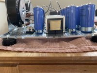
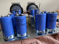
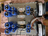
J Zen PSU coming along. A bit heavy for the plate. Need some support it would seem, iron sag.
Attachments

That’s Towelie. No, but seriously, can you guess that towels main purpose/normal purpose?
Oooh yes! Made me [emoji4] … We had to have them by the dozen (and they‘re sometimes still in use, 11yrs later…)
- Home
- Amplifiers
- Pass Labs
- Aleph J illustrated build guide