What voltage drops do you read across R6 and R30 of the dysfunct chan, compared to the working one?
In the good channel R6 is 3.1 volts, R30 varies, starts low at 1 mv, then rises rapidly to 50 mv or so. R6 is 562 ohms R30 is ten ohms. In the bad channel R6 is 100 mv and falling, R30 is steady at 85 mv.
Q2 should only be dissipating about 1/4W so I too would suggest checking along
the front end. Please measure the voltages across D1, R6, R7, R8 and R30 and
confirm what you are using for R8 and R7.
the front end. Please measure the voltages across D1, R6, R7, R8 and R30 and
confirm what you are using for R8 and R7.
Is your R30 10 ohms?
Anyway, your R7 voltage is problematic. If you turn R7, does the voltage
across it change? If it doesn't then please check the soldering of the jfets and
R7 again. If the soldering is good then you probably have damaged jfets or
R7.
Anyway, your R7 voltage is problematic. If you turn R7, does the voltage
across it change? If it doesn't then please check the soldering of the jfets and
R7 again. If the soldering is good then you probably have damaged jfets or
R7.
Ok, thanks very much for your help. I will check these things tomorrow. Yes R30 is ten ohms. Should It be more, like 100 ohms?
The exact value of R30 isn't important. I only asked so I can ascertain the current
in the front end. Your 85mV measurement across R30 means the correct
current (8.5mA) is flowing to Q1a and Q1b.
But you have 0V across R7. If you adjust R7 and see no change in voltage
then either R7 is shorted out or no current is flowing from Q1a down to R7
and you'll probably want to desolder parts and test them.
I just love it when the esteemed Mr. Hui hunts down a problem. Thanks for the lesson in DIY problem solving!
Well 3U/400 UMS and 3U Deluxe rear panel all look to be not an option. ...... pain in the keister. 🙄
blah blah blah....
So I pulled the trigger on the 4U Deluxe and I think everything I need from the DYIaudio store to start my Aleph J build. From AnTek the AS-3220 - 300VA 20V toroidal. Hoping the 20V spec is within nominal range - as they are out of the 300VA 18V units.
Question. What is the first single tap (Purple) described here? https://www.antekinc.com/content/AS-3220.pdf - how is it used?
Lastly, am I correct in thinking that none of the snubber components are required in the PSU BOM? I'm also forgoing all the diodes and going with Full Bridge Rectifiers - I think diagnostically speaking it's a cleaner build that way.
Last edited:
Aleph J noise in one channel, offset not stable
Hi!
First of all, I would like to thank everyone here in diyaudio, and in particular in the Pass foruns. I've been learning a lot, by first buildng an ACA, then a F5 and now an Aleph J (reusing chassis and PSU from F5). They are all different but great in their own way. And a very special thank you to Nelson Pass, for sharing all those beautiful designs.
The Aleph J was finalized around a week ago and everything went totally smooth. Bias (400 mV) and offset (around 0mV) achieved with no issues, and stable with either lid off or on (different values for the trim pots, of course). It gets hotter than the F5 but the heatsinks hang around the 50ºC mark, so I guess it's ok.
Really great sound (I like it better than the F5 and that is saying a lot) and dead silent on both channels.
That is, until today... 🙁 the left channel developed a noticeable noise, a kind of "modulated" hiss (I mean, like the old tape hiss but it's not constant, almost like tube rush). It's loud enough to be heard about 3m from a 89dB speakers, on a fairly quiet room.
I switched input cables (balanced) between left and right and the noise kept coming from the left channel, so it was not my DACs fault, or the cable.
I decided to short the inputs and the noise remained. Since I had shorted the inputs I decided to remove the speaker cable and measure the offset and it was around 150 mV and rapidly changing... 🙁. The right channel offset remained rock solid and around 1mV.
Checked bias and it was ok on both channels.
Readjusted offset (not easy, it went down but suddenly up while rotating the trim pot) and it now oscillates rapidly between 5 mV and 12mV.
BTW, while listnening to music it's ok, can't really tell a problem other than the noise, sound seems "normal".
Touching ground, etc, makes no difference on the hiss.
Any ideas on what this could be? I guess the noise and strange offset may be related...
Some component that was kind of DoA? All semiconductors and boards bought on diyaudio store, all other components came from Mouser. No problems until now from either source, on all the things I bought.
I'll check all the connections and solder, of course, but this kind of noise seems more related to (say) a capacitor that went bad (they are new, so early failure can happen) or a JFET?
I can post pictures of the boards, if that helps.
It has been a week of silence and stable measurements, until today. I guess problems like a bad solder would probably be revealed earlier (like it happened on my ACA).
Any input would be greatly appreciated, so I can order the most probable components to go on replacing them... 🙂
Again, thank you so much for all the knowledge distilled here and for all the patience for this kind of issues.
NightFlight,
You connect the purple wire on Antek transformers to chassis ground. It’s an electrostatic shield between the primary and secondary.
Best,
Anand.
You connect the purple wire on Antek transformers to chassis ground. It’s an electrostatic shield between the primary and secondary.
Best,
Anand.
Lastly, am I correct in thinking that none of the snubber components are required in the PSU BOM? I'm also forgoing all the diodes and going with Full Bridge Rectifiers - I think diagnostically speaking it's a cleaner build that way.
Only use snubbers if you have the equip to measure what values to use for Cs1, Rs1 and Cx1. Or, check out the thread «Quasimodo - results only». Your donut might be there. And btw, 6L6 always says to try without first, and see if snubbers make a diff or not. If you do that, you’ll prolly have to solder the snubber network under the PCB if you choose to try. If your first build, omit them, my cents.
Andy
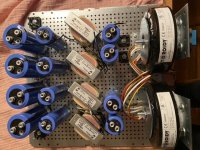
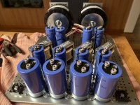
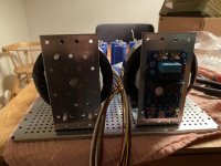
So, after 2M5 of DIY abstinence, I finally got around to sorta making a proof of concept for the PSU originally destined to supply a pimped BA-3, then Aleph J, then landing on J Zen.
It’s not pretty, but hey, it was never meant to please eyes but ears.
It’s a tight fit. Seen here is my first attempt of a P2P PSU layout using big caps, in a dual mono CLC setup. Donuts are 300vA Toroidys with 18v secondaries. Softstarts to go behind them close to the front plate in a vertical setup. Plan is fastonless and soldered only, with fuses x 2 a’la Choky at the back plate. Decouplers across the last set of caps is also a part of the plan. 10uF of course.
This feeds two Graets bridges per PSU, and snubbers will be added by soldering directly to bridge faston terminals. Thanks to the Quasimodo results thread, I got values that should work well. I believe they came from Darrr. Thank you!
From bridges to Nichicon LNR 25v caps @ 47kuF a piece per rail. Then into 10mH @ 5A Hammond inductors, ending in the final caps where thea idea is to have enough filtering to make ripple measurable but of zero consequence, at the same time as providing ooomph for the bottom end. PSU was modeled and though I can’t remember exact ripple current at the rails, it was miniscule. Sent the Models to Choky so I can probably dig em up. Per rail there is 1x47kuF per rail, and one 100kuF cap per rail as the last caps. Total capacitance is 0F77, 0F388 per PSU, and 0F194 per rail. Since current draw will be half per rail as compared to using one PSU, ripple is allready low and with this I hope to kill it almost completely. We will see.
At the corners of the back of the bottom plate, are ground loop breaker bridges. I also plan to have made two triangles of aluminium plate to make as a quiet ground as possible at the last sets of caps, also inspired / ripped off from our dearly beloved would be adoptee of Papa / son of Zardoz, Choky.
Hope to get this PSU finished in a month or so. Progress is sloooow. Thinking is, as always, my main occupation. Which is also slow, and seemingly seldom ends in something audible. Best get going 🙂
Thanks to all who have inspired and helped me, and answered my endless questions about established truths. Wish me luck. At first startup, I am crossing my fingers. Will the softstarts do the job without modification? Will I have to use a standard thermistor setup instead? Will something blow? Will the inductors couple with the circuit and make hummmmm? Time will tell.
At least, building a P2P PSU really gets you closer to how the PSU works. Risk of messing things up is of course higher. But don’t we like risk? I know I like a bit of it. And I only had one fire so far.
Regards,
Andy
Attachments
Last edited:
damn, how many of these 6L6 sent abroad ?
It’s not that many have been sent, it’s that I’m only sending them to people I know will build them, and fairly quickly.

(Which is wayyyyy better than I’ve managed… I’ve been so busy with real life I can’t see straight lately… no worries, things will calm down in another month I think.)
I promise I will get it running come Christmas. That might also mean a month though. Sometimes I get things done in a jip 🙂
Btw, saw that video of you promoting the pilot course. Kudos. It’s the kind of personality and attitude that gets people out of their chairs and gives them that little kick to start believing in themselves. I am one of the positively affected. Thank you, Jim!
Btw, saw that video of you promoting the pilot course. Kudos. It’s the kind of personality and attitude that gets people out of their chairs and gives them that little kick to start believing in themselves. I am one of the positively affected. Thank you, Jim!
Last edited:
Only use snubbers if you have the equip to measure what values to use for Cs1, Rs1 and Cx1. Or, check out the thread «Quasimodo - results only». Your donut might be there. And btw, 6L6 always says to try without first, and see if snubbers make a diff or not. If you do that, you’ll prolly have to solder the snubber network under the PCB if you choose to try. If your first build, omit them, my cents.
Andy
Thanks Andy. Its a first build. I've built a couple bottlhead projects (Crack/Mainline). Enough to learn to solder and basically paint by number. This project is going to make me think a bit more. I'll add the subbers later - I like to tinker with finished projects anyhow.
I'm slowly getting through the thread and picking up tidbits as I go. Next is just getting all the parts in. The CBSA is planning to strike in a couple days. That should make for a nice shipping snag.
- Home
- Amplifiers
- Pass Labs
- Aleph J illustrated build guide