More smoke
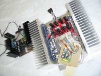
To recap, when I first plugged in my newly completed Aleph J it blew fuses, which I solved by using larger amp, slow blow fuses. Then it read 21 negative volts DC offset on the right channel. (Left was OK.) Following advice in the thread, I looked for loose parts or a burr causing a short. I suspected Q7 because I had mangled one of the prongs. I didn't find anything except that the Q7 screw was loose, so I tightened it. Also following the thread, I changed my inputs so that in(-) was bridged to a ground, while I used another ground for the input connection. Then I switched on again and smoked R11. Removed board, replaced R11 and Q7 while I was at it and cleaned up a few less than perfect solder connections. Replaced board, turned on and now the two resistors adjacent to Q3 and Q6 immediately smoked. I should add that when I first tried to get rid of the negative 21 reading, I turned the offset pot quite a bit to no avail. I checked it this morning and I've got 49 ohms at R7, about 1.1K at R27. So clearly I need to adjust those. All my other DIY projects just worked, so I'm feeling a bit fuddled.
To recap, when I first plugged in my newly completed Aleph J it blew fuses, which I solved by using larger amp, slow blow fuses. Then it read 21 negative volts DC offset on the right channel. (Left was OK.) Following advice in the thread, I looked for loose parts or a burr causing a short. I suspected Q7 because I had mangled one of the prongs. I didn't find anything except that the Q7 screw was loose, so I tightened it. Also following the thread, I changed my inputs so that in(-) was bridged to a ground, while I used another ground for the input connection. Then I switched on again and smoked R11. Removed board, replaced R11 and Q7 while I was at it and cleaned up a few less than perfect solder connections. Replaced board, turned on and now the two resistors adjacent to Q3 and Q6 immediately smoked. I should add that when I first tried to get rid of the negative 21 reading, I turned the offset pot quite a bit to no avail. I checked it this morning and I've got 49 ohms at R7, about 1.1K at R27. So clearly I need to adjust those. All my other DIY projects just worked, so I'm feeling a bit fuddled.
Attachments
back to basics
desolder all active parts , check them either with diode test (BJTs) or in matching jig (mosfets, JFets) (in fact - BJTs - just replace them)
check resistors , lift one leg if needed
replace what's for replacing
be sure of proper mosfet mounting - clean surfaces , mica&goop, screw torque
power up and set
This no doubt all good advice, but some of it is above my head. What is a BJT? I have a good Fluke multimeter; can I check the active parts with that? I mounted my mosfets with silicone pads, and did screw torque by feel. I'm not a complete newb but I pretty much build these things like a "paint by numbers" routine, so any explanation is helpful.
... I pretty much build these things like a "paint by numbers" routine...
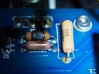
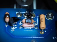
Here is a suggestion for you to incorporate into your routine. Make sure that Dale resistor values are readable from the top, as in one of the pictures I posted here:
http://www.diyaudio.com/forums/pass-labs/224881-aleph-j-universal-mounting-spec-10.html#post3385712http://
Notice that I made them readable from the same direction as the components' designators printed on the PCB. That will make it possible for other people to help you check their values from pictures you post. That is especially important when you have values which may lead to confusion, as in the case of the Aleph J: 221R, 22K1, 221K.
I have the Chipamp PCB's if I wish to build the Aleph J what changes to the schematic that is listed in the first post would I need to use the boards I currently have. Are the parts and values the same irregardless of which PCB's I use? I am pretty new to amp building so please excuse me if this seems like a dumb question. 🙂
Here is a marked up schematic that shows how to build a J from the Chipamp Aleph pcb. It was created by a kind member, not me. However, you will still need to remap the parts numbers to the official AJ schematics.I have the Chipamp PCB's if I wish to build the Aleph J what changes to the schematic that is listed in the first post would I need to use the boards I currently have. Are the parts and values the same irregardless of which PCB's I use? I am pretty new to amp building so please excuse me if this seems like a dumb question. 🙂
Attachments

I recommend blowing $25 on a set of store Aleph J boards and make it easier especially since you have said you are pretty new to amp building. Considering what it cost to build a FW clone I would just spend $25 on correct boards. I built an Aleph 30 with the chimpamp boards as my first build. I still have the boards stuffed around here somewhere but if I were to build an Aleph J I would buy new store Aleph J boards. I am a cheap diyer too but considering the cost to build a FW clone $25 is not that much.
Thanks for the replies. I definitely hear what your saying about buying the other boards, and saving some headaches in the process. It wouldn't be any problem to use the Chipamp PSU board for the Aleph J as long as the correct filter caps are used. I think it's 60,000uf per channel.
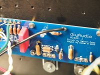
Aleph J uni mounting Store Boards
Hi.
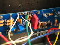
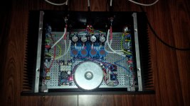
The PSU should be possible to use- i have 15mF 25V 22mm in diameter from DigiKey in there.
The Amp is running with 340mV biased.
All parts are placed careful who advised here.
The JFet- good matched in 10mA Idss, BJT- BC Type, IRFP250M on Output bought by Mouser.
Sound is very clear with full bodied tones- i like it to listen, non fatigue.
In neighborhood you can see a ACA.
join in to Aleph J. Cheers.
Hi.
The PSU should be possible to use- i have 15mF 25V 22mm in diameter from DigiKey in there.
The Amp is running with 340mV biased.
All parts are placed careful who advised here.
The JFet- good matched in 10mA Idss, BJT- BC Type, IRFP250M on Output bought by Mouser.
Sound is very clear with full bodied tones- i like it to listen, non fatigue.
In neighborhood you can see a ACA.
join in to Aleph J. Cheers.
Attachments
I have the Chipamp PCB's if I wish to build the Aleph J what changes to the schematic that is listed in the first post would I need to use the boards I currently have. Are the parts and values the same irregardless of which PCB's I use? I am pretty new to amp building so please excuse me if this seems like a dumb question. 🙂
Check the file in post #4, that should also help:
http://www.diyaudio.com/forums/pass-labs/204748-aleph-briangt-boards.html
Me and my friends are building Aleph J's on the Chipamp boards as well. Started a while a go 🙄. But if I would start now, certainly would buy the diyAudio store boards. If we run into any issues when we start firing up everything, I might still be inclined changing to the diyAudio boards...
I made small adapter PCB's for mounting the 2SJ74 and ZTX550 transistors. If you are still adamant on using the Chipamp boards and you want, I still have 2 lying around somewhere.
Another option to make use of the BrianGT Aleph board is to build a Zen Mod Babelfish out of it!!
Difficult to choose
I have started building my Aleph J now and when going through my stuff to see if I had capacitors home to use I found that I have both Nichikon Muse and Nichikon Fine Gold home at 220 uF but 50V. I have decided to use these since they are already home but which should I go for...... Muse....Gold.😕😕
You can follow my mixed thread at;
http://www.diyaudio.com/forums/pass-labs/295715-my-first-aleph-pass-labs-experience.html
The Muse, black and gold case, are the more relaxed in presentation. The FG can get kinda " shouty" if used exclusively. YMMV.
sole position of important cap is that one feeding Aleph CCS with modulation - middle right one , on schematic
rest are filter bloody ones , pretty irrelevant which type , as long decent pro quality is used
in fact , same applies even for that 220uF (in modulation path) , if bypassed with proper solid cap (preferably 0u47-1u)
on the other side - you can omit that one on negative input , just put shortie instead
I found that I have both Nichikon Muse and Nichikon Fine Gold home at 220 uF but 50V.
I have decided to use these since they are already home but which should I go for...... Muse....Gold.😕😕
Both are wonderful capacitors. Use the ones that are a better fit into the PCB.
It's been a steep learning curve getting into diy audio, but totally addicted! Tried a few SSMH, a F5 and a chip amp or two.... With varying degrees of success.... But this build, with better skills and knowledge and an awesome design and forum has left me smiling! LOVE the sound of this one! Very happy!!! Thanks chaps!
Attachments

- Home
- Amplifiers
- Pass Labs
- Aleph J illustrated build guide