The resistor with the chipped coating is fine. You don't need to patch it either ... They are pretty much indestructible unless they crack in half.
The gain of the amplifier will be down if the -N is not grounded using the rca inputs.
What he said😀
The resistor with the chipped coating is fine. You don't need to patch it either ... They are pretty much indestructible unless they crack in half.
Thanks, that's reassuring but Soundhappy's offer is really great, so I sent a PM to him to replace the resistors.😉
Thanks, that's reassuring but Soundhappy's offer is really great, so I sent a PM to him to replace the resistors.😉
Hi Folkdeath95
You got PM

Greetings
Hi Folkdeath95
You got PM
Greetings
Soundhappy, very kind of you to help out a fellow diyer.
Cheers,
Dennis
@Marra and wdecho,
thanks for the response. Going this weekend on a little holiday with the family, after that i hope to fire up the aleph somewhere in the next 2 weeks.
thanks for the response. Going this weekend on a little holiday with the family, after that i hope to fire up the aleph somewhere in the next 2 weeks.
Slowly but surely, as is my style, I make progress. I stand on the shoulders of giants and wouldn't be this far without those that have come before me.
Boards stuffed:

Thank you all!
Jim
Boards stuffed:
Thank you all!
Jim
I have a question about the ground on the Aleph board, on the pictures in the building guide i see a bridge connection between the gnd and the -in, am i seeing this correct?
Correct.
No particular reason -- that wire was near at hand when I soldered it.this is a very thin wiring, why is this?
😀 😀 😀
Slowly but surely, as is my style, I make progress.
Looking good! Carry on!!
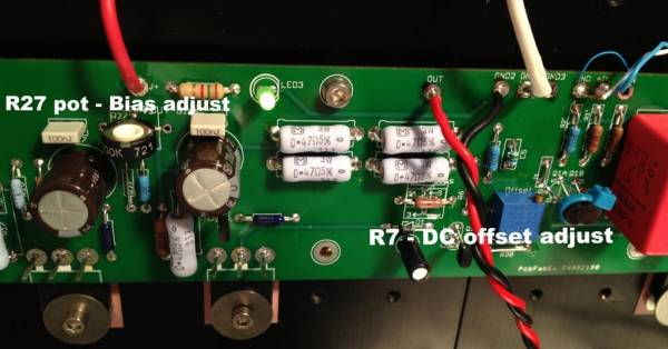
Hey guys, it looks like the white cable that runs from the psu to the boards is cut into halve and then soldered to gnd1 and gnd3, Am i seeing this correct or is this just my imagination?
Soundhappy, very kind of you to help out a fellow diyer.
Cheers,
Dennis
Yes, I appreciate it a lot. I replaced the cracked resistors with the two new Soundhappy sent me.
Boards are now ready:
An externally hosted image should be here but it was not working when we last tested it.
Mikael
Hey guys, it looks like the white cable that runs from the psu to the boards is cut into halve and then soldered to gnd1 and gnd3, Am i seeing this correct or is this just my imagination?
Which pic are you talking about?
Yes, I appreciate it a lot.
Hi Folkdeath95
Congratulations great diy work !
I like your photo with amp on old stone traditional wall in Bretagne.

Hey guys, it looks like the white cable that runs from the psu to the boards is cut into halve and then soldered to gnd1 and gnd3, Am i seeing this correct or is this just my imagination?
In that photo it does look that may be true.
But no, the white wire is just attached from PSU gnd to the amplifier board.
And even if the wire were split and attached to both of those pads, electrically it would make no difference at all.
What do you think about good low noise separate power supply for jfet's (e.g. TPS7A4700) ?
It's worth it ?
It's worth it ?
Glad to help.
Remember, the only stupid question is the one not asked... 😉
Use this forum to help you succesfully complete your project, we all want to see you succeed, and as a bonus, you get a fantastic amp to listen to !
Remember, the only stupid question is the one not asked... 😉
Use this forum to help you succesfully complete your project, we all want to see you succeed, and as a bonus, you get a fantastic amp to listen to !
What do you think about good low noise separate power supply for jfet's (e.g. TPS7A4700) ?
It's worth it ?
impossible
input Jfets and lower mosfet must stay on same voltage potential
ok, thank you 🙂
What about C3 ? Is this possible to use e.g. Jantzen MKP 220uf ? I know it's huge, but maybe there is chance to improve something. If no, please let me know which cap is the best for this purpose.
What about C3 ? Is this possible to use e.g. Jantzen MKP 220uf ? I know it's huge, but maybe there is chance to improve something. If no, please let me know which cap is the best for this purpose.
- Home
- Amplifiers
- Pass Labs
- Aleph J illustrated build guide