Pass DIY Addict
Joined 2000
Paid Member
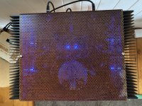
Here are the images, Zen. They aren't the greatest images, but they are what I have right now. The boards are populated as per the BOM from the DIYA store page. I cut the ground trace to separate the speaker ground from PSU ground and replaced it with either a 10R or 20R (I don't remember which) in order to tame a little bit of hum that I get when both inputs are connected. The big PIO cap has since been replaced with yellow MKC cap.
The PSU is an outboard configuration that I also used with my F4 and M2 amps without any problem. It uses a single Teabag PSU board which features a CRC configuration. It uses a 3-wire umbilical cord with Neutrik termination. Inside the amp, each channel gets its own pos and neg PSU cap.
The PSU is an outboard configuration that I also used with my F4 and M2 amps without any problem. It uses a single Teabag PSU board which features a CRC configuration. It uses a 3-wire umbilical cord with Neutrik termination. Inside the amp, each channel gets its own pos and neg PSU cap.
Attachments

Anyone recommend a capacitor for 3300pf cap in the ac supply line? I’ve not messed with line capacitors before, and unsure what kind of specs (aside from capacitance) I need to shot for.
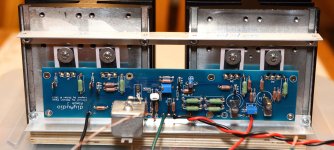
Here are the images, Zen. They aren't the greatest images, but they are what I have right now. The boards are populated as per the BOM from the DIYA store page. I cut the ground trace to separate the speaker ground from PSU ground and replaced it with either a 10R or 20R (I don't remember which) in order to tame a little bit of hum that I get when both inputs are connected. The big PIO cap has since been replaced with yellow MKC cap.
The PSU is an outboard configuration that I also used with my F4 and M2 amps without any problem. It uses a single Teabag PSU board which features a CRC configuration. It uses a 3-wire umbilical cord with Neutrik termination. Inside the amp, each channel gets its own pos and neg PSU cap.
The capacitor that is second from the top is not wired to the same terminals as the other three.
Pass DIY Addict
Joined 2000
Paid Member
The capacitor that is second from the top is not wired to the same terminals as the other three.
The top two caps feed the channel in the left side of the image. The two bottom caps feed the channel in the right side of the image.
I understand that. However, the red wires to the second cap (positive pin) is to a different pin than at the other three caps.
Pass DIY Addict
Joined 2000
Paid Member
OMG 😱  I've been looking at this for a long time and just didn't see that.. 😱
Given the current that circulates through here, I'm lucky this didn't cause a real problem for me. I bet this is the cause for both of my problems: hum and the turn-off chirp.
This is easy enough to explore tonight! Thank you!
I've been looking at this for a long time and just didn't see that.. 😱Given the current that circulates through here, I'm lucky this didn't cause a real problem for me. I bet this is the cause for both of my problems: hum and the turn-off chirp.
This is easy enough to explore tonight! Thank you!
Pass DIY Addict
Joined 2000
Paid Member
Bingo! Moved the wires on the cap (duh) and now everything is great! Amp is absolutely silent even with my ear right in the speaker and the power-off chirp is gone. Thanks for the extra set of eyes, I can't believe I didn't see that...

Just starting a build, either AJ or F6 or both. I'll be building it into a 5U DIY audio case. First I'm starting on the DIYaudio PSU CRC all good so far..would 3k3 4W bleed off resistors be OK.
TIA
TIA
Pass DIY Addict
Joined 2000
Paid Member
Laverda - 3k3 4w is great. I use 2k2 2w in mine, so you'll just have slightly slower bleed off of voltage.
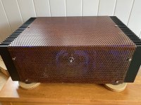
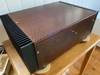
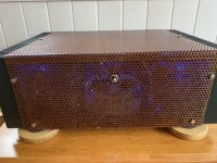
Roo2: is that a copper mesh sheet? Looks great!
My completed chassis for the Aleph-J is linked in my signature.
Roo2: is that a copper mesh sheet? Looks great!
My completed chassis for the Aleph-J is linked in my signature.
- Home
- Amplifiers
- Pass Labs
- Aleph J illustrated build guide