Thanks bnorrish. I will use some of your parts and ideas and bring some new ones to the table. Especially thinking of adding the Panasonic 3W resistors also as an option.
Post #68 - was that the final layout, schematic?
-R7, R8 are 500 ohm pots?
- What about R27 - what value pot?
- J1 and J2 are resistors - what values?
-R7, R8 are 500 ohm pots?
- What about R27 - what value pot?
- J1 and J2 are resistors - what values?
Thanks bnorrish. I will use some of your parts and ideas and bring some new ones to the table. Especially thinking of adding the Panasonic 3W resistors also as an option.
Go nuts Panasonic blue vs Vishay brown 🙂
Post #68 - was that the final layout, schematic?
-R7, R8 are 500 ohm pots?
- What about R27 - what value pot?
- J1 and J2 are resistors - what values?
- For R7 pots min 1K, i prefer 2K
- R8 you can use 500 ohm pots, but value for R6 min 560 ohm
- J1 and J2 are gate stoper. You can jumpered or use resistors, wit value from 0 to 220 ohm
CMIIW
Didiet
IT is better to have more headroom wit hpot. Ideally, you hav a fixed value resistor and then another por in series.. Once you get it biased, you can replace with permanent resistor of matching value.
6L6
I see on the original schematic from Nelson that R7 is 1K. So it just makes sense for a 2K multi-turn pot. I usually prefer the 25 turn ones, not the flat ones which only provides 1 turn resolution.
Feedback welcome as usual.
I see on the original schematic from Nelson that R7 is 1K. So it just makes sense for a 2K multi-turn pot. I usually prefer the 25 turn ones, not the flat ones which only provides 1 turn resolution.
Feedback welcome as usual.
C6 : 100nF - 1uF or just leave empty
R28,29 : depend on LED, 3-5Kohm
R30 : wire jumper, or 1 - 100ohm
Didiet
R28,29 : depend on LED, 3-5Kohm
R30 : wire jumper, or 1 - 100ohm
Didiet
Yep and change to Led2 and Led3. Just to show all voltage rail are ok (request from 6L6)
And C6, C7, R30, J1, J2 are sugested by ZenMod
Didiet
And C6, C7, R30, J1, J2 are sugested by ZenMod
Didiet
Last edited:
I am making an assumption that C2 and C3 can be 16V electrolytics. Obviously something like Elna Silmic II or Nichicon FG or KZ.
Last edited:
I see on the original schematic from Nelson that R7 is 1K. So it just makes sense for a 2K multi-turn pot.
Yes, a 2k is perfect there.
The 500ohm is a reference to the Aleph Jango, and not appropriate to the Aleph J -- my mistake.
Good catch, BTW!! 😛
That's a good thing to make note of on the BOM - please illustrate why you are making the choices and also what other type of peices can work. This way people can learn something about parts selection, and also have alternatives in mind if their suppliers don't have the 'right' part. 🙂I usually prefer the 25 turn ones, not the flat ones which only provides 1 turn resolution.
6L6, Didiet; please check if C2 and C3 can accommodate capacitors with a lead spacing of 7.5mm.
I will be happy to send you actual measurements from the PCB once I have them in hand, Didiet can tell you the dimensions in the meantime.
I think the best way is not to replace a resistor by a pot. if you use a resistor in series to the pot resistance can never below the value of the resistor and the pot gets easier to adjust. ...
BOM updated with more trimpot info.
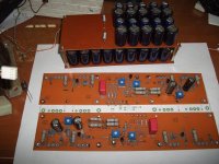
I would like to have some input from experience DIYers out there. From an image of the PCB I can see that only the 3386K model single turn pot will match the pin arrangement. However, I see that neither Mouser nor Digi-Key have stock of that specific model. Advice will be valued. I have also attached the Bourns 3386 data sheet, so if one of you out there can have a look at that it would be very helpful.
I also tried the Vishay model 36P as specified on the PCB, and did not have luck either although it does seem that RS stock some values for the Vishay range.
Attachments
Last edited:
- Home
- Amplifiers
- Pass Labs
- Aleph J for Universal Mounting Spec