Zen Mod, I had spares, so I replaced the ZTX parts again while I saw your note. This didn't change the behavior.
I had a meter on the speaker output and on the MOSFET source resistor. I turned R7 in until it clicked, then backed it out until it clicked again. Throughout, I saw no voltage across the resistor. The voltage on the speaker output went from +19V to +20V, but the increase seemed not to be due to my R7 adjustments.
So far, the only non resistor/capacitor component I haven't changed are the JFETs. I keep looking for a solder join overlapping pads, etc. I don't see anything.
well
time to power off and pull JFets out and test them in small matching jig
you can use even 9V battery instead of said 12V source
if there are no shorts measured between mosfet pins ( all 3 of them, pins) , they're likely alive and leave them for now
back R7 to minimal , just in case
just in case - did you confirmed actually having +24Vdc and -24Vdc on your channel pcbs, ref. to GND?
called 24V , unloade it is 24-ish, while when amp is operational and PSU loaded, it'll be 22V-ish
Attachments
Last edited:
Zen Mod, the LSJ74/LSJ74 is listed ad PP. Does that mean it's a P-Ch FET? Based on the schematic, I'm to measure milliamps between the battery negative and the drain?
And, if I understand you correctly, I can determine if they're bad my testing for shorts between the pins without the jig?
And, if I understand you correctly, I can determine if they're bad my testing for shorts between the pins without the jig?
your LSJ are P channel
test them in jig, you're not able to test them properly just with multimeter
I said - test mosfets for shorts with DMM, on pcb
it'll do for now
though, you must try to be consistent - I've just read- in one moment that you had "One of them passes current between the source and drain in both directions" , only that you later tried to power amp again
it calls for all mosfets dismantle , whatever complicated that's for you, and checking them too
best thing you can do now is to remove all mosfets and check with simple buzz test between all pins
after that, useful pause - search on forum for "mosfet matching jig" , or go to FW site and read article
in short - if any ofthem is Dodo, you probably doesn't need checking rest of them, you need 2 new matched pairs
Thanks for all the help, Zen Mod. I need to transition my focus to dinner cooking and partner attention 🙂 She's a devout music listener, but I can only retried to "the lab" for so long before I start to get some looks 🙂 I'll follow up in the morning.
MOSFETs and JFETs are difficult to test unless you put them in a test circuit.
I found this little device invaluable, it tests almost any discrete component.
All-in-1 component tester transistor diode capacitor resistor inductor meter xe | eBay
I found this little device invaluable, it tests almost any discrete component.
All-in-1 component tester transistor diode capacitor resistor inductor meter xe | eBay
Thans KatieandDad. I figured I could check for a short between leads without removing the JFETs.
Zen Mod, I found no short between any of the leads. There's ~42R between source and drain, measured in either direction - but it's also like that on the working board. I'll remove them and test if that would be useful; but I'd prefer not to if there's something else I can check.
Zen Mod, I found no short between any of the leads. There's ~42R between source and drain, measured in either direction - but it's also like that on the working board. I'll remove them and test if that would be useful; but I'd prefer not to if there's something else I can check.
be specific, make difference between JFets ( input LTP ) and Mosfets (output stage)
explain "One of them passes current between the source and drain in both directions"
explain "One of them passes current between the source and drain in both directions"
Zen Mod: Sorry about that. Q1A and Q1B measure 38-42R across source and drain, regardless of the meter polarity.
Here are my measurements, + indicating where I put the positive probe:
Q1A:
+S,G: Unmeasurable
S,+G: Unmeasurable
+G,D: Unmeasurable
G,+D: Unmeasurable
+S,D: 41.8R
S,+D: 33.2R
Q1B:
+S,G: 41.3R
S,+G: Unmeasurable
+G,D: Unmeasurable
G,+D: Unmeasurable
+S,D: 37.3R
D,+S: 38.7R
Here are my measurements, + indicating where I put the positive probe:
Q1A:
+S,G: Unmeasurable
S,+G: Unmeasurable
+G,D: Unmeasurable
G,+D: Unmeasurable
+S,D: 41.8R
S,+D: 33.2R
Q1B:
+S,G: 41.3R
S,+G: Unmeasurable
+G,D: Unmeasurable
G,+D: Unmeasurable
+S,D: 37.3R
D,+S: 38.7R
for God's sake, pull them out and check with matching jig
test output mosfets in situ, with that procedure and write here
test output mosfets in situ, with that procedure and write here
Zen Mod: I really appreciate your help. I misread your previous instructions. I now see. you meant I should test for shorts with the MOSFETs in place, but need to test the JFETs removed.
I don't have a breadboard; so I'm going to see how I can get something going otherwise. I'll post my measurements when I work it out.
I listened to a bunch of my favorite material, with my pre-amp in mono, on the working side today. This is the best solid state amp I've heard! I'm very much looking forward to fixing the broken channel!
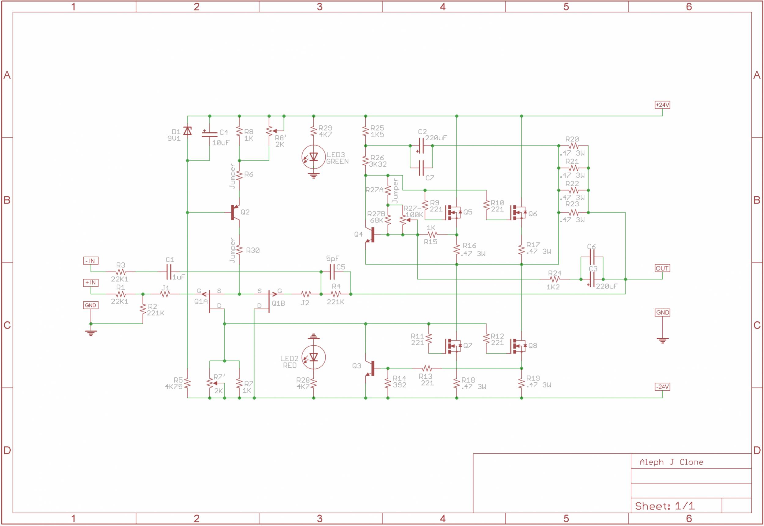
Zen Mod: Using the schematic provided in post #102, substituting a 9V battery for the 12V source, I measured 10.7ma through one LSJ74, and 10.8ma through the other.
I'm not sure I have the skill or tools to remove the MOSFETs without damaging them. Does the information about the JFETs provide any other paths to pursue?
Forgot to mention: The PS is putting out 23.2V +/- when the working channel is being powered by it.
I'm not sure I have the skill or tools to remove the MOSFETs without damaging them. Does the information about the JFETs provide any other paths to pursue?
Forgot to mention: The PS is putting out 23.2V +/- when the working channel is being powered by it.
Last edited:
None of the MOSFETs have shorts between pins. They're still in the board.
Should I re-install the JFETs?
Should I re-install the JFETs?
Last edited:
reinstall them, be sure to check isolation between mosfet drains and heatsinks, tighten properly
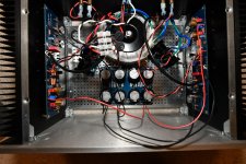
prior to powering on , post set of well lit and big enough pictures, so we can check did you connect it in same way as functional channel
prior to powering on , post set of well lit and big enough pictures, so we can check did you connect it in same way as functional channel
which channel is bad , on pic - left or right?
edit: ignore that , wiring looks OK on both channels
now, you know the recipe - two DVMs , one on output, second across any mosfet source resistor (say R16 or R18)
if you have 3rd DVM - check presence of both rails on pcb , ref. to gnd, after powering on
check voltage across R8, you know the value from previous posts
no load on output, input shorted
start with minimized R7 (trimpot) , which you can confirm prior to powering on , taking ohmic measurement between negative rail and Q3 collector, or negative rail and common of R11/R12
measuring in same points you can confirm rise of voltage across R7 trimpot , when you're fiddling with
Last edited:
- Home
- Amplifiers
- Pass Labs
- Aleph J - First Test Issues / No Sound / Blinking LEDs