KatieandDad: I think it was just initial break-in. It began to sound rich and full after an hour.
I took the chassis apart to perform a final mounting of the heat sinks, and upon reassembly, one channel is unable to be adjusted to 0v offset on the speaker outputs. It's wired the same as before. I'm trying to figure out why. Anybody have an idea of where to start?
I took the chassis apart to perform a final mounting of the heat sinks, and upon reassembly, one channel is unable to be adjusted to 0v offset on the speaker outputs. It's wired the same as before. I'm trying to figure out why. Anybody have an idea of where to start?
KatieandDad: I think it was just initial break-in. It began to sound rich and full after an hour.
I took the chassis apart to perform a final mounting of the heat sinks, and upon reassembly, one channel is unable to be adjusted to 0v offset on the speaker outputs. It's wired the same as before. I'm trying to figure out why. Anybody have an idea of where to start?
have some numbers?
I removed the board and am currently looking for cold solder joints. Everything measured find before I removed it; so I'm guessing I had a bad solder joint and jostled it.
I went over all the solder joints and re-assembled. With the R7 all the way in, a can get the voltage down to 1.33V - but not below. Is it possible I damaged a component when I didn't have the power connected properly? This is the side that I was testing with during that period.
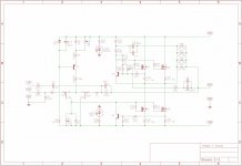
Zen Mod: I measure 8.51V across R8. BTW, this was originally a pot and was replaced by a 1K resistor, as per 6L6's recommendation.
8V5 looks OK
be sure to have RCA input grounded, no load at output
now, tell me voltage across R16 and describe how you organized:
R7 and R7'
R27,R27A,R27B
edit : confirm do you have +1V37 or -1V37 , as output offset
be sure to have RCA input grounded, no load at output
now, tell me voltage across R16 and describe how you organized:
R7 and R7'
R27,R27A,R27B
edit : confirm do you have +1V37 or -1V37 , as output offset
I'm measuring 0V across R16. I set the meter to mv to make sure there was nothing - and there's indeed 0v as best as I can tell.
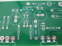
I'm not sure how the schematic translates to the pcb, exactly. There's an R27 position for a pot in the board, and I've installed a 100k pot in that position. There's also a position for a resistor - and I've jumped this, according to the build guide. Those were the only two R27 positions I saw.
The shield of the input is jumped to ground on the board side.
Attachments
wowbagger: I'm using these:
Keratherm Transistor Insulators – diyAudio Store
Bottle: What would you like me to photograph and what info can I provide?
This is frustrating. I've been listening to the working channel, and it sounds great 🙂
Keratherm Transistor Insulators – diyAudio Store
Bottle: What would you like me to photograph and what info can I provide?
This is frustrating. I've been listening to the working channel, and it sounds great 🙂
Keratherm Transistor Insulators
Even experienced builders have found pads like Keratherm easy to puncture if not careful -
I've had a few problems with shorting the mosfet to the sink over the years. Usually, I'd not de-burred the mounting hole sufficiently after drilling/tapping and some lip would pierce the silpad and short the mosfet. One time it was a nearly microscopic aluminum shaving that got stuck in the silpad that caused a short.
If *all* you did was disassemble and reassemble the boards from the heatsinks, such a short could possibly be something that could occur when doing so.
Last edited:
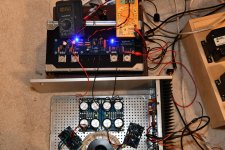
New photos of the connections from PSU to the boards, photos of the side not working.
Please bring a lamp or two near your amp and have lots of light in there so it focuses well and the photos are nice and sharp.
R27 - you have the jumper in the vertical position and the potentiometer in the horizontal, yes?
Voltage measurement, just to verify, you have your meter in DC volts, correct?
Zen wanted to know -
This would be with the black probe of the meter in the speaker black and the red probe in red.
Please bring a lamp or two near your amp and have lots of light in there so it focuses well and the photos are nice and sharp.
R27 - you have the jumper in the vertical position and the potentiometer in the horizontal, yes?
Voltage measurement, just to verify, you have your meter in DC volts, correct?
Zen wanted to know -
edit : confirm do you have +1V37 or -1V37 , as output offset
This would be with the black probe of the meter in the speaker black and the red probe in red.
6L6: Thanks for offering to help!
I disconnected the working board to keep the connections easy to see. As you can (hopefully) determine from the pic, vertical R27 is jumpered. Horizontal has the pot.
I left the meters in place so you could see how they're connected and what they're set to.
Once again, upon re-assembly, my measurements are different. I'm now getting +22.9V on the output, with no voltage measured for bias.
Please let me know if I can send a pic focusing on a particular section.
Attachments
Last edited:
replace all ZTX for start
be sure to check isolation of mosfets from heatsink after mounting them back
edit: check mosfets for shorts between pins while pcb is out; use beep test on your DMM
be sure to check isolation of mosfets from heatsink after mounting them back
edit: check mosfets for shorts between pins while pcb is out; use beep test on your DMM
Last edited:
- Home
- Amplifiers
- Pass Labs
- Aleph J - First Test Issues / No Sound / Blinking LEDs