Just about the only way to improve on <a href="http://www.diyaudio.com/forums/showthread.php?s=&threadid=2451">tortello's beautiful Zen headphone amp</a> is to go for an Aleph headphone amp. The advantages are the balanced FET front-end and the DC-coupled output. This design is specified to put 500mW into Grado headphones, or other phones with about 32Ω impedance. It should also drive a small speaker, and indeed has done so in a breadboard incarnation.
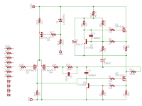
Right now the only thing I'm not liking is the high value of the current sense resistor. I used it in my breadboard mockup but I might change it for something smaller.
One channel shown.
Right now the only thing I'm not liking is the high value of the current sense resistor. I used it in my breadboard mockup but I might change it for something smaller.
One channel shown.
Attachments
Would it be OK to drive HD580 Sennheiser Headphones with this amp ? The input inmpedance is much higher ... 300 Ohms.
Re: Missing component ?
All that junk on the left is for the input coupling. I didn't draw it because it isn't that interesting.
Nicke said:Shouldn´t there be a resistor between R14 & R15 coupled to ground ?
All that junk on the left is for the input coupling. I didn't draw it because it isn't that interesting.
Re: Missing component ?
What Nicke means is, you're showing 100% feedback. A resistor where he suggests would reduce feedback, adding actual gain.Nicke said:Shouldn´t there be a resistor between R14 & R15 coupled to ground ?
Nicke
Re: Re: Missing component ?
Thats right ...
Is it unity gain stable as drawn ?
paulb said:
What Nicke means is, you're showing 100% feedback. A resistor where he suggests would reduce feedback, adding actual gain.
Thats right ...
Is it unity gain stable as drawn ?
"As drawn" is incomplete. Trust me, those resistors over on the left really do go in the circuit. I just got tired of clicking the mouse. You obviously get the idea.

How is it going?
I have some kristian PCB boards lying around for an Aleph 4 which I like to turn into a headphone amp for my Sennheiser 580!
Edwin
I have some kristian PCB boards lying around for an Aleph 4 which I like to turn into a headphone amp for my Sennheiser 580!
Edwin
Hi Edwin. It's going well. I got a Sun 411 SCSI case to put the amp in and modified it for XLR connectors. I'm still in the process of drawing the printed circuit board. Hopefully I will finish it next weekend.
I also increased the design rail voltage to 14V.
I also increased the design rail voltage to 14V.
jwb said:Hi Edwin. It's going well. I got a Sun 411 SCSI case to put the amp in and modified it for XLR connectors. I'm still in the process of drawing the printed circuit board. Hopefully I will finish it next weekend.
I also increased the design rail voltage to 14V.
Did you listen to it? How does it sound? What did you use before building this Aleph headphone amp?
Edwin
Powersupply
So, how about the PS?
Are you going for an unregulated supply, or are you using a regulated?
I've been schetching on a regulated PS based on the circuit explained in the A75 article part 2, which I will use for my Aleph headphone amp.
//magnus
So, how about the PS?
Are you going for an unregulated supply, or are you using a regulated?
I've been schetching on a regulated PS based on the circuit explained in the A75 article part 2, which I will use for my Aleph headphone amp.
//magnus
Re: Powersupply
I have listened to one channel on a breadboard. It sounds rather bad! But it is powerful and the bad sound is a result of poor layout, I hope.
My previous headphone amp was the Sheldon Stokes design seen on Headwize.
I am using four separate Sulzer regulators with AD797 error amp and ZTX869 for the pass transistor. The power dissipation is low enough to not require a big power transistor.
Cheers
Edwin Dorre said:
Did you listen to it? How does it sound? What did you use before building this Aleph headphone amp?
I have listened to one channel on a breadboard. It sounds rather bad! But it is powerful and the bad sound is a result of poor layout, I hope.
My previous headphone amp was the Sheldon Stokes design seen on Headwize.
swede said:So, how about the PS?
Are you going for an unregulated supply, or are you using a regulated?
I've been schetching on a regulated PS based on the circuit explained in the A75 article part 2, which I will use for my Aleph headphone amp.
I am using four separate Sulzer regulators with AD797 error amp and ZTX869 for the pass transistor. The power dissipation is low enough to not require a big power transistor.
Cheers
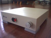
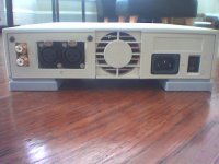
Case finished
These Sun 411 SCSI cases are awesome for audio projects. The SCSI connector cutout is just the right size for two Neutrik XLR jacks. And, the case comes fully shielded contains a switched, fused power entry module. What more could I ask for?
These Sun 411 SCSI cases are awesome for audio projects. The SCSI connector cutout is just the right size for two Neutrik XLR jacks. And, the case comes fully shielded contains a switched, fused power entry module. What more could I ask for?
Attachments
Member
Joined 2002
Hello Marcello. Output offset is trimmed to zero, unmeasurable when the amp is warmed up. Why do you mention it?
By the way, your amp is my inspiration. Very nice job!
By the way, your amp is my inspiration. Very nice job!
Hello ,
thanks for the compliment, but I've only turned the Pass' design into a smaller world.
In your design, the lack of a capacitor between R20 and the ground might bring about this problem, but if it works...
Very nice the "Sun Look"!!
Cheers
Marcello
thanks for the compliment, but I've only turned the Pass' design into a smaller world.
In your design, the lack of a capacitor between R20 and the ground might bring about this problem, but if it works...
Very nice the "Sun Look"!!
Cheers
Marcello
- Status
- Not open for further replies.
- Home
- Amplifiers
- Headphone Systems
- Aleph headphone amp