Can I use inductors with a wire size of 16.5 gauge (1.2mm) for the PSU? Can it withstand the current from the transformer? The inductor has a DCR of 0.63ohm. Thanks
iceman,
depends on your bias current. If you use the standard 2A the current through the choke will also be 2A. So it'll dissipate 0,63Rx2x2=2,5watts. This shouldn´t be a problem.
william
depends on your bias current. If you use the standard 2A the current through the choke will also be 2A. So it'll dissipate 0,63Rx2x2=2,5watts. This shouldn´t be a problem.
william
wuffwaff said:iceman,
depends on your bias current. If you use the standard 2A the current through the choke will also be 2A. So it'll dissipate 0,63Rx2x2=2,5watts. This shouldn´t be a problem.
william
Thanks.
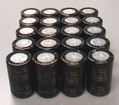
I'll be using 20 x 15,000uF (300,000uF total, 150,000uF for each channel) 63V Nichicon caps for the PS and 43CTQ100 (40A,100V) schottky barrier rectifiers for the bridge.
Attachments
schottky barrier rectifiers
nice choice.
10 ohm NTC thermistor should be fine... according to Nelson, they will sit at a lower resistance inside a warm amp chassis.
see http://www.diyaudio.com/forums/showthread.php?s=&threadid=759 for more info on current limiting.
nice choice.
10 ohm NTC thermistor should be fine... according to Nelson, they will sit at a lower resistance inside a warm amp chassis.
see http://www.diyaudio.com/forums/showthread.php?s=&threadid=759 for more info on current limiting.
I've just finished building the Schottky Bridge Rectifier for the Aleph 5 PSU.
Noise measurement of Schottky Bridge Rectifier and standard bridge rectifier:
http://icceman1.tripod.com/Schottky_Bridge.htm
Noise measurement of Schottky Bridge Rectifier and standard bridge rectifier:
http://icceman1.tripod.com/Schottky_Bridge.htm
Attachments
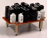
Interesting pic. I can't tell what's between or on the heatsinks. Did you use 8 diodes in the bridge, or did you sandwich each package between the heatsinks?
Best,
Erik
Best,
Erik
Since the heatsinks are so close together, won't the heatsink get welded together if they accidently touch each other?

The bridge module is for one channel of the Aleph 5. There's 2 bridge on the module, 1 for each rail. There's 2 diodes in 1 43CTQ100 (common cathode, 20A for each leg, 40A per device) and it's in a TO220 package.eLarson said:Interesting pic. I can't tell what's between or on the heatsinks. Did you use 8 diodes in the bridge, or did you sandwich each package between the heatsinks?
Best,
Erik
Pics of the Aleph 5 PSU (1 channel) :
10mv / 0.5ms
An externally hosted image should be here but it was not working when we last tested it.
An externally hosted image should be here but it was not working when we last tested it.
An externally hosted image should be here but it was not working when we last tested it.
An externally hosted image should be here but it was not working when we last tested it.
10mv / 0.5ms
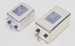
Is it advisable to use RF filters at the AC line for the Aleph 5 PSU? I'm thinking of using this filter:
These RF filters give high attenuation in both differential and common mode. Extended low frequency performance makes them suitable for industrial frequency converters, motor drives and switch mode power supplies. A combination of X2 and Y class capacitors and a high inductance toroidal choke give high performance especially in applications where interference is frequent and intensive. Electrical connection is by 250 (1/4in.) terminals for soldering or push-on receptacles. (Please refer to the Connectors - Terminals/Test Leads section).
Approvals: VDE, FI (only applicable to 6A and 10A types).technical specification
Line frequency 50/60Hz
Operating voltage 115 to 250V ac
Insulation resistance 6000M (100V dc)
Leakage current 2 x 2·1mA (3·6A : 2 x 0·45mA) (250V 50Hz)
Typical attenuation 75dB
Climatic category IEC68 25/85/21 DIN 40040
Temperature range -25°C to +85°C
Attachments
I'm using a switched, fused, filtered IEC mains socked for mine to kill several birds with one stone.
Going back to my question a couple of posts ago, it would appear that the only advantage to using 2 bridges is to share the load. Beefy bridges are so cheap it makes you wonder why they bother.
Going back to my question a couple of posts ago, it would appear that the only advantage to using 2 bridges is to share the load. Beefy bridges are so cheap it makes you wonder why they bother.
when you use large cans in PSU, you get inductance from the inner coils of the capacitor.
I read somewhere that we should put a small (+-4uF) polyester capacitor to reduce the PSU capacitors indutance.
Is this correct?
if so why doesn't NP put them on his amps like aleph 5 ?
is there any down side?
is it really necesary?
I read somewhere that we should put a small (+-4uF) polyester capacitor to reduce the PSU capacitors indutance.
Is this correct?
if so why doesn't NP put them on his amps like aleph 5 ?
is there any down side?
is it really necesary?
Thanks. They are 2.2mH Jantzen Baked Wire Coil Inductors (used for speakers crossover). 16.5 gauge.skaara said:icceman did you made coils yourself, wery nice PSU😎
- Status
- Not open for further replies.
- Home
- Amplifiers
- Pass Labs
- Aleph 5 PSU