Hi all. I m in the midst of testing my Aleph 5 mono with Mark Finnis's pcb. When connect to the speaker (one channel) nothing seems to happen. When I switch off the amp, the LED stays illuminate for 20 minutes before finally dim. I matched the N fets according to a diagram by Kristijan. They are value at 3.03 to 3.20V. Is this possible? I used a 19V to a 150ohm resistor. The power from the PSU is measured at 37.75V. The speaker terminal measured at 0.07V. What is the problem??
Thanks in advance.
Thanks in advance.
The LED stays on pretty long because you probably have some monster power supply caps and no sort of bleeder resistor for the caps to bleed off the charge.
Seems like there runs no current at all trough your FETs. You can check if there runs current. You can measure the voltage over R11 it must be around 4 Volts. You can also see if the voltages are the same of each channel.
Pictures are always welcome. Helps a lot sometimes.
In fact, by looking at the pics I posted in the Mini A thread, rtirion spotted the wrongly inserted Zener diodes my circuit. The Zener has to be orientated correctly to make the currentsource work.
So be sure to post pictures and check the orientation of the Zeners in the current source.
In fact, by looking at the pics I posted in the Mini A thread, rtirion spotted the wrongly inserted Zener diodes my circuit. The Zener has to be orientated correctly to make the currentsource work.
So be sure to post pictures and check the orientation of the Zeners in the current source.
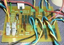
Right, I have some zeners reverse and the transistors are BC550, which has the CBE on the reverse as oppose to MPSA18. I have rectified these but problem persists. When I switch on the amp, the speaker moved forward and the lights are not on now. I have attached some pics. Thanks guys, i appreciated your help.
Attachments

The cone moves out and stays there? Or does it move back again? And the lights are not on? If the lights are not on something might draw a whole lot of current and will cause the supply-voltage to drop. Not a good thing. In that case you should also hear a buzz from the transformer as the core saturates.
I hope you have some cheap test speakers...
We now need some numbers. Do you have the aleph 5 service manual? On page 6 there's the schematic with some voltages.
Please measure the DC voltage of the following points (take a look at the schematic):
- Voltage across the Zener and the source-resistor in the CCS
- Voltage across all the BC550s from collector to emitter
- Voltage across the output-FETs' source resistors and the FETs themselves (from drain to source)
- Voltage across the FETs of the CSS and the differential pair (also from drain to source)
- Voltage from drain of the IRF9610 in the CCS to ground
- Also please measure the supply voltages in reference to ground and the output-offset.
This should give some clues.
zener (Z5) at Q3 - IRF9160 measured at 8.89
Z2 measured at 0.10
Z1 measured at 0.13
Z3 at 0.43
Z4 at10.26
Q5 - BC550 between C and E measured at 0.56
Q6 - BC550 between C nad E at 0.0
R11 measured at 5.29
R14 measured 0.0
Q1 - IRF9610 between G and S measured 0.5
Q2 - IRF9610 between G and S measured 0.53
All output resistors measured at 0.0
Z2 measured at 0.10
Z1 measured at 0.13
Z3 at 0.43
Z4 at10.26
Q5 - BC550 between C and E measured at 0.56
Q6 - BC550 between C nad E at 0.0
R11 measured at 5.29
R14 measured 0.0
Q1 - IRF9610 between G and S measured 0.5
Q2 - IRF9610 between G and S measured 0.53
All output resistors measured at 0.0
How do I measure the gnd and the output offset? Is it between the star gnd and the output at the speaker terminal?
pmchoong said:How do I measure the gnd and the output offset? Is it between the star gnd and the output at the speaker terminal?
Yes, DC offset : measure DC value just between your 2 output terminal + and - (star grd).
Manu
Its too much ...
(should less than 50mV)
Same issue on both channel?
Voltage accross R14 is near 0.
You don't have any current going through it, no voltage drop; so lower output mosfets don't conducts hence you get plain rail voltage (- 35V) at the output.
You could check if there is something wrong with R14 (to high res)
and/or Check Q1 and Q2
You should have about 4 V Vgs.
You could try to replace them, taking care of electrostatics ...
Manu
same problem exist
I have canibalised the board, measured all resistors and zeners and re-soldered them back to a new board with new matched IRF 9610 and new MPSA18 transistors but the problem persisted. This is the measurement :
Output between gnd is measured at 43.3mV
R14 at 3.528V
MPSA 18 at Q4 measured at 3.525mV
MPSA 18 at Q5 measured at 11.7mV
R40 & 41 measured at 0.0
R42 at 0.7mV
R22 to R25 measured at 0.7mV
R11 measured at 5.12V
R14 at 3.528V
Z5 at 9.05V
Q3 IRF between G and S is measured at 3.93V
Q2 IRF between G and S measured at 3.79V
Q2 and Q3 mosfet warms up but not Q1
When I measured Q1 between G and S, a buzzing sound is audible at the speaker when I touch the G of the mosfet
Many thanks to those who help.
Rodeodave said:
- Voltage across the output-FETs' source resistors and the FETs themselves (from drain to source)
- Voltage across the FETs of the CSS and the differential pair (also from drain to source)
- Voltage from drain of the IRF9610 in the CCS to ground
- Also please measure the supply voltages in reference to ground and the output-offset.
This should give some clues.
Q3 from drain to source is measured at 29.48V
Q2 from drain to source at 41.30 V
Q1 from drain to source at 37.8V
Q6-8 IRFP240 from drain to source measured at 37.5
Q18-20 IRFP240 from drain to source measured at 38.5V
How do I measured the drain of IRF9610 to ground?
Get the measurement from each IRF9610 between D and G from the star Gnd of PSU?
I soldered R9 with a 220K resistor and R19 with a 220 resistor. Now when I turn on the amp, the LED lights up bright in a split of a second and then stay half dim. When turn off, the LED shuts out and then brightens up again with a very dim light. Also, when i turn on the amp, the speaker moves inwards and stay at that position. Thanks for help.
- Status
- Not open for further replies.
- Home
- Amplifiers
- Pass Labs
- Aleph 5 problem