I've been messing around with this long enough and I'm ready to seek help... That being said: I've built a Aleph 3 and I'm having a terrible time figuring out a problem I'm having with one channel. The unit starts up and I dialed in bias and offset and just when I plugged in my iPhone to check it, it went pop. My phone that is. The 3.5mm jack blew up on my phone.
I checked and found I had offset voltage on the input from one channel reaching .6volts and the other side was at 0. I blew a capacitor on the side with the voltage. After replacing it I checked input offset and found it had returned to 0 on both sides. I put the project down a couple days and thought it over.
Today I returned to it and I measured voltage at the input and found one channel to have 0, like it should, and the other to have -27volts! The one with the voltage issue is the one that has performed correctly all this time without any failure. I measured across the voltage rails and I have 55 volts, but 53 from the negative and 2 from the positive to chassis ground. I also have -27volts on the "ground" coming off my supply capacitor bank.
All my voltage reading are off on this channel and I have no idea where to start. I disconnected the power supply from the amplifier board and it performed as it should, + and -27 volts. As far as I can tell, the negative voltage is feeding back through the entire system through the ground and I'm not sure why or why the negative voltage is so high. One last piece of evidence is I found a blown diode on this channel as well, but after replacing it nothing changed.
Any ideas on where to start or what to check would be extremely helpful. Thank you.
For starters, as always, post pics. Ideally post a schematic of the actual build showing wiring and with voltage measurements annotated.
Check all solder joints for bridges.
Check all solder joints for bridges.
schematic and pictures
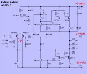
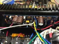
Here are some pictures as well as a schematic with measurements. Only difference as far as I can tell in the schematic is that I'm using 2 variable resistors to adjust bias and offset. All the measurements are done checking voltage using chassis ground.
Here are some pictures as well as a schematic with measurements. Only difference as far as I can tell in the schematic is that I'm using 2 variable resistors to adjust bias and offset. All the measurements are done checking voltage using chassis ground.
Attachments

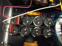
using solid core fatties soldered to pcb is recipe for disaster
remove them , remove pcbs from heatsink and inspect is there any damage to traces
also - try power supply with some load
say that 100W bulb across one rail will be as 25W load
remove them , remove pcbs from heatsink and inspect is there any damage to traces
also - try power supply with some load
say that 100W bulb across one rail will be as 25W load
I ran a couple 8ohm 25watt resistors across the rails and measured. They stated to smoke after about 30 seconds, but I got the measurements before. About 27volts on both sides. Will this suffice for testing the power supply under load? Clearly having no idea that solid core is bad for this situation, could you please explain why? I have the pcb off the heat sink and cannot see any damage. The diodes are good and the resistors measure good and are not burnt. Really all I can think to do is remove the transistors and check them as well as the board traces. I could also remove the capacitors and measure/replace them too.
I just really have no idea what would cause this to fail and then cause the voltage irregularities I'm measuring. My only guess would be the mofsets on the positive side? Is there a way to test them in the circuit? Maybe similar to matching then?
I just really have no idea what would cause this to fail and then cause the voltage irregularities I'm measuring. My only guess would be the mofsets on the positive side? Is there a way to test them in the circuit? Maybe similar to matching then?
-27volts on the "ground" coming off my supply capacitor bank. --> that mean isolate Mosfet to heatsink problem...i think.
-27volts on the "ground" coming off my supply capacitor bank. --> that mean isolate Mosfet to heatsink problem...i think.
Yep! Thank you.
using solid core fatties soldered to pcb is recipe for disaster
Why is that, ZM?
more vibration issues than thermal cracking
one thing was solid core in solder lugs/turrets in toob era , another thing is pcb
disclaimer - if there is eyelet or through-hole wire pad on pcb ...... do whatever you want 😉
edit : Jaccolina is , these days , even more grumpy than usual

one thing was solid core in solder lugs/turrets in toob era , another thing is pcb
disclaimer - if there is eyelet or through-hole wire pad on pcb ...... do whatever you want 😉
edit : Jaccolina is , these days , even more grumpy than usual
I'm not sure of any other reasons, but I can report that after I swapped out the solid cores, I found the unit to have a quieter background.
even more grumpy than usual
Me was supposed to lie under a palm tree in may, but then came the flu.
My son is driving with friends to a rental cottage in France next month, and who's the fool that pays for it.
All work and no play makes humpty dumpty a nasty btch.
Solid copper is a rigid body compared to stranded, a wire will act as a cantilever at the solder pad.
Aka, fixed beam at both ends with uniformly distributed load.
Combination of vibration, cross-section area moment of inertia (I), and mass.
Attachments
madskaman,
Sounds like you have a mis-wiring somewhere. Start in the power supply.
Check the transformer secondary wiring is correct. Amp off. Unplug the power cord from the amp. Unplug the secondaries from all the bridge rectifiers. You are looking for continuity. Find the pairs of secondary windings. Use a meter on Ohm reading or continuity reading. If you connect the probes at 2 leads and get a reading or a beep, they are a pair. If no reading or beep, they are not a pair.
Remove all power supply connections to the amp boards. Be sure you do not let a power supply (PS) wire drop into the chassis or touch anything. Remove connections from 0v on supply bank.
All this is a precaution. Measure the Plus and Minus supplies to 0v reference. At this point, we can't be sure it's a place between the cap banks. Use VDC multi-meter probe and test 0v on the cap bank to the ground lug on the IEC connector. It's also an assumption that the ground lug on the IEC isn't being fed voltage directly. Once you know 0V is 0V at the cap banks, then test the Plus and Negative side of the power supply banks. Both side should read the same voltage.
Before connecting any power to the amp boards, go over all the wiring for the amp boards: plus to speaker outs, where does the speaker ground go to? Amp board or 0v at amp cap bank? Check input connections to the amp boards. Pay attention to power ground and signal grounds where do they go?
It looks as though I've made a terribly embarrassing, and potentially dangerous mistake. I didn't use proper isolation on the transistors to the heatsinks. I've corrected the problem and the amp works as designed now. I'm feeling like I got away with one at this point. I'm waiting on a few CL-60s for the power supply and then after I clean up some wiring I think I'll be done. Except, I might remove the variable resistors, measure them, and replace them with low noise fixed ones. Is this something worth doing?
Cool. Take deep breathe and move on. 🙂
Which variable resistors? Bias and offset should stay.
Looking at the schema it was designed for auto bias.
Maybe follow the schematic.
Which variable resistors? Bias and offset should stay.
Looking at the schema it was designed for auto bias.
Maybe follow the schematic.
Last edited:
- Status
- Not open for further replies.
- Home
- Amplifiers
- Pass Labs
- Aleph 3 diy problem with one channel