The Culprit was found
Last Friday afternoon I spent an hour or two in the lab trying to find out what caused the amp to fail. Again, it meant to desolder some important components. (which I don't like, and neither does the PCB. some pads have been seriously damaged by the repeated soldering / desoldering).
However, the culprit was found!
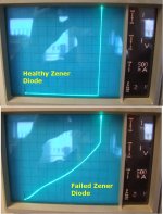
Z5 failed in parameter drift. The curve tracer showed that for lower zener currents, the voltage drop was much less than specified, and varied a lot with temperature. It also showed some hysteresis effect (probably causing the noise).
This caused the diff pair to enter current starvation, and hence, operation ended up far away from the properly balanced point.
I replaced the zener and Amp no. 2 is again playing in my workshop 🙂
/me happy now....
Last Friday afternoon I spent an hour or two in the lab trying to find out what caused the amp to fail. Again, it meant to desolder some important components. (which I don't like, and neither does the PCB. some pads have been seriously damaged by the repeated soldering / desoldering).
However, the culprit was found!

Z5 failed in parameter drift. The curve tracer showed that for lower zener currents, the voltage drop was much less than specified, and varied a lot with temperature. It also showed some hysteresis effect (probably causing the noise).
This caused the diff pair to enter current starvation, and hence, operation ended up far away from the properly balanced point.
I replaced the zener and Amp no. 2 is again playing in my workshop 🙂
/me happy now....
Ah that brings up a point I was going to mention, I have found quite a bit of variance in zener diodes and have had peoblems with this in circuits I have designed for use in my current profession. Maybe this is another item we should test select in the aleph amps.
Re: The Culprit was found
I'm glad ..........

Bakmeel said:....
However, the culprit was found!
.........
I'm glad ..........

Re: The Culprit was found
When the amp doesn't work, it's always something real.
No voodoo here...

Bakmeel said:However, the culprit was found!
When the amp doesn't work, it's always something real.
No voodoo here...

Component Failure Modes
Because component failure modes are also of interest to my work environment, I took some time to test the failed zener diode. Perhaps the result is of interest to this community as well...
I put the failed zener on a curve tracer (an invaluable, but also unaffordable piece of equipment when building solid state amplifiers). Attached is two photographs of the display. (This device is probably older than I am).
I am using 1N4696 zener diodes (datasheet here) for the constant current source feeding the diff pair.
The horizontal axis shows voltage, 1V/div. The vertical axis shows current, 1mA/div.
The healthy diode shows a nearly square behaviour and is very stable (as it should be according to the datasheet, minimum zener current is in the order of microamps).
The faulty diode is almost like a resistor until there's about 9mA flowing through it. At 4.5mA, the nominal current in the A2, zener voltage is around 5V. Almost half of what it is supposed to be. Furthermore, the resistive part of the "failed" curve was behaving very noisy and even had a hysteresis effect. Combined with a resistor bias, the voltage at the CCS mosfet gate must have been extremely noisy and instable. (perhaps explaining the hissing noise I heard.)
As an effect, the diff pair went in starvation, and barely had enough current to achieve proper regulation.
I guess Zen Mod had a good feeling from the start 😉
Attachments
Re: Component Failure Modes
when ?
when I wrote "Fugly!" ?
😀
Bakmeel said:.........
I guess Zen Mod had a good feeling from the start 😉
when ?
when I wrote "Fugly!" ?
😀
Zen Mod said:are you using matched devices for input LTP ?
remove temporary Z1,Z2,Z3,Z4
replace both Q3 and Z5 ....... 15mA isn't enough through CCS ;
I have found lately several specimens of zenners to not have proper voltage
MythBusters say: Myth Confirmed.... 😎
This thread reads like a "cliff hanger". Very good.
From the wear and tear on the solder pads of your printed circuit boards, will you continue to deploy them or is it time to place new PCB's in the "twin Towers"?
All the best!
From the wear and tear on the solder pads of your printed circuit boards, will you continue to deploy them or is it time to place new PCB's in the "twin Towers"?
All the best!
Re: Component Failure Modes
My master

Manu
Bakmeel said:
I guess Zen Mod had a good feeling from the start 😉
My master

Manu
Showcase!
For now I will use them as is. The damage to the pads is not so terrible if you don't need to re-work them anymore. If ever I think these beasts need an upgrade, I will consider a new front-end PCB (with LS disconnection relay implemented).
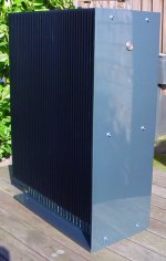
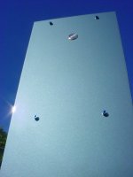
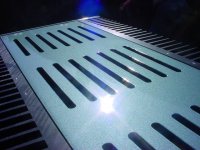
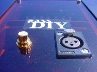
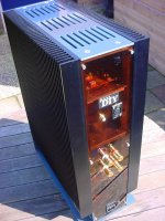
Today was a sunny day, which wasn't forecast, but I took the opportunity to take a photoshoot on the amps 🙂
first pic:
mosfets said:From the wear and tear on the solder pads of your printed circuit boards, will you continue to deploy them or is it time to place new PCB's in the "twin Towers"?
For now I will use them as is. The damage to the pads is not so terrible if you don't need to re-work them anymore. If ever I think these beasts need an upgrade, I will consider a new front-end PCB (with LS disconnection relay implemented).
Today was a sunny day, which wasn't forecast, but I took the opportunity to take a photoshoot on the amps 🙂
first pic:
Attachments
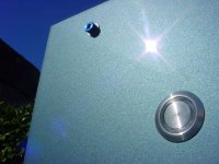
number 6:
It's beamer metallic paint yeah... 😀
For Dutch fellow DIY-ers with similar wishes, here's the paintshop that did the work: Spuiterij van Gemert (Dordrecht)
It's beamer metallic paint yeah... 😀
For Dutch fellow DIY-ers with similar wishes, here's the paintshop that did the work: Spuiterij van Gemert (Dordrecht)
Attachments
what can I say ......
if you're just half good man as your amps are nice and neat ...... then - it was real pleasure messing in this thread
if you're just half good man as your amps are nice and neat ...... then - it was real pleasure messing in this thread

The pleasure was fully mutual.... Thanks for all the help and great responses... Off to the next project (whatever that will be)
Bakmeel said:The pleasure was fully mutual.... Thanks for all the help and great responses... Off to the next project (whatever that will be)
a turntable PSU... ;-)
converting 230V +-50Hz to 230V 50Hz and or 67,5hz
Aleph 2 not hot enough?
I have just finished one monoblock of my Aleph 2. It makes good sound, but I am wondering whether there is something wrong with my build. I was expecting the heatsink to be scorching hot, but turning the amp on for more than 1 hour and measuring the temperature at one of the MOSFETs mounting bolt, it settles at only 56.7 degree C (around 20C ambient). The heatsinks are only warm and I can put my hands on the heatsinks forever.
My heatsink is the 10.080" profile from HeatsinkUSA:
10.080" - HeatsinkUSA, LLC Store
I am using 4 pieces of 9 inch long section per monoblock (3 MOSFET mounted on each 9 inch piece). It is guesstimated at 0.80 C/W/3 inch. So theoretically my setup is around 0.80/(4x3 inches) = 0.067 C/W.
More info on the build:
1kVA trafo
16 x 15000 uF electrolytics (2.7 mH inductor)
Power supply output at 50V
IRFP244 matched within 10mV
Parts BOM per kk-pcb (Pass Labs ALEPH-2 DIY amplifier PCB)
Maybe I should not worry about all these and just enjoy it. 😀
- Status
- Not open for further replies.
- Home
- Amplifiers
- Pass Labs
- Aleph 2 - The Final Build
