A friend of mine built two Aleph 2 mono blocks for me about 17 years ago, long before I started doing any building myself. They were fine but run very, very hot (in hindsight the Modushop 4U 400mm cases are too small) and there was something not quite right when you compared them to my factory Aleph 3. I know, a 2 will sound different than a 3, but the 2s just don't sound as relaxed (for want of a better word) than the 3 or for that matter my diy F4s.
I knew some of the parts he used were not what I would choose today, so the cement block 1R and 0R47 resistors will be replaced by 5W metal films. The 220uF caps of unknown brand will also be replaced, but I am not sure yet what to use. I have 220uF Silmic IIs (25V and 35V) and Nichion Muse FG (25V) in my drawer and some Nichion Muse KZ (50V) and Nichion Muse ES bipolar (50V) on order. Any suggestions which to put where would be appreciated.
I also noted that in an old thread, the ZVP3310A was mentioned as a good replacement for the 9610s. http://www.diyaudio.com/forums/pass-labs/172987-zvp3310-good-choice-input-fet-aleph-30-a.html
It as an old thread, so I would be interested to hear if other people have since tried this and what their results were. I know they are not in stock at Mouser, Digikey or Farnell/Element14 but I think I bought about 25 ZVP3310A many years ago, so could hope to get a few matched pairs (if I can find them haha).
The power supply currently consists of:
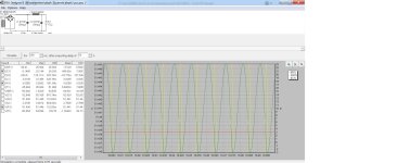
The first problem I noted was of course that in this configuration, the rails will be much higher than spec (according to psu designer about 51V with an 11mV ripple). As the mains voltage where I currently live is 240V, I can expect another 2V, giving me rails of just over 53V. I understand from the service manual that the circuit will adjust bias automatically, resulting in a lower bias, so I expect dissipation to remain 300W per monoblock.
What alarmed me is that according to psu designer, the ripple the first 47000uF cap will see is double the rating of the cap (max. 13.2A according to datasheet). Not good.
The amp has not seen that many hours (I have too many amplifiers 😎) but the first cap could be seriously aged by this maltreatment. How can I check the condition of the cap? If it is still OK, I assume swapping the hard driven first cap with the hardly stressed second one will prolong life?
Obviously, the ripple the first cap sees has to be significantly reduced. Ideally the rail voltage should be lowered as well (the circuit will automatically increase the bias to accomodate for this). Just adding capacitance does not seem the best solution.
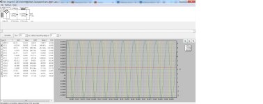
I remembered something EUVL said about adding resistance in the psu (when I tried to get rid of hum in my Aleph H). I played around with psu designer and came up with the following simple solution: Convert the CLC design into RCLC by adding 0R75 resistance before the first cap. (N.B. I also tried LCRC using the same values, but psu designer showed excessive voltages experienced by the bridge rectifier and a higher ripple at the load).
According to psu designer, with the RCLC psu the first cap ripple is less than 50% what it was previously (now within datasheet spec) and the rail voltage drops to 45V (from 51V). The resultant load ripple (simulated as 17R in CLC and 13R is RCLC to give about 150W dissipation per rail, to compensate for the circuit automatically adjusting the bias to keep dissipation constant) hardly changes (I surmise it is probably more dependent on the size of L and C2).
I assume this solution will add quite a bit of heat (psu designer calculates 6A RMS at 4V5 RMS through the 0R75 resistor, so about 54W per mono block). I will have to add fans for these Aleph 2s anyway, and especiially to survive the extra heat. I have some old PC fans of various sizes but am unsure if placement in the enclosure will give enough relief. Has anyone tried this?
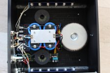
Having had plenty of trouble with radiated noise recently while testing a newly built pumpkin in my shed, I am wondering if the placement of the coils in my amps could be improved upon. Ideally I would move the transformer and coils to another box (perhaps even try a regulated psu) but a 4 box stereo amplifer really is a bit too much. I have attached a photo of the current layout (don't take any notice of the old soft start to the right of the bottom coil; it has since been replaced by an NTC).
Will a steel cover over the transformer (if I can find one that big) and/or coils (assuming I have enough room to do this) make a big difference?
Any suggestions are welcome!
I knew some of the parts he used were not what I would choose today, so the cement block 1R and 0R47 resistors will be replaced by 5W metal films. The 220uF caps of unknown brand will also be replaced, but I am not sure yet what to use. I have 220uF Silmic IIs (25V and 35V) and Nichion Muse FG (25V) in my drawer and some Nichion Muse KZ (50V) and Nichion Muse ES bipolar (50V) on order. Any suggestions which to put where would be appreciated.
I also noted that in an old thread, the ZVP3310A was mentioned as a good replacement for the 9610s. http://www.diyaudio.com/forums/pass-labs/172987-zvp3310-good-choice-input-fet-aleph-30-a.html
It as an old thread, so I would be interested to hear if other people have since tried this and what their results were. I know they are not in stock at Mouser, Digikey or Farnell/Element14 but I think I bought about 25 ZVP3310A many years ago, so could hope to get a few matched pairs (if I can find them haha).
The power supply currently consists of:
- Talema TRT1000240 1kVA 230V primary 2 x 40V 12.5A secondaries
- Standard GBC type bridge rectifiers
- CLC :
- 47000uF/63V F&T GM
- Intertechnik aircoil 2.2mH 0R46 (1.4mm copper)
- 47000uF/63V F&T GM
The first problem I noted was of course that in this configuration, the rails will be much higher than spec (according to psu designer about 51V with an 11mV ripple). As the mains voltage where I currently live is 240V, I can expect another 2V, giving me rails of just over 53V. I understand from the service manual that the circuit will adjust bias automatically, resulting in a lower bias, so I expect dissipation to remain 300W per monoblock.
What alarmed me is that according to psu designer, the ripple the first 47000uF cap will see is double the rating of the cap (max. 13.2A according to datasheet). Not good.
The amp has not seen that many hours (I have too many amplifiers 😎) but the first cap could be seriously aged by this maltreatment. How can I check the condition of the cap? If it is still OK, I assume swapping the hard driven first cap with the hardly stressed second one will prolong life?
Obviously, the ripple the first cap sees has to be significantly reduced. Ideally the rail voltage should be lowered as well (the circuit will automatically increase the bias to accomodate for this). Just adding capacitance does not seem the best solution.
I remembered something EUVL said about adding resistance in the psu (when I tried to get rid of hum in my Aleph H). I played around with psu designer and came up with the following simple solution: Convert the CLC design into RCLC by adding 0R75 resistance before the first cap. (N.B. I also tried LCRC using the same values, but psu designer showed excessive voltages experienced by the bridge rectifier and a higher ripple at the load).
According to psu designer, with the RCLC psu the first cap ripple is less than 50% what it was previously (now within datasheet spec) and the rail voltage drops to 45V (from 51V). The resultant load ripple (simulated as 17R in CLC and 13R is RCLC to give about 150W dissipation per rail, to compensate for the circuit automatically adjusting the bias to keep dissipation constant) hardly changes (I surmise it is probably more dependent on the size of L and C2).
I assume this solution will add quite a bit of heat (psu designer calculates 6A RMS at 4V5 RMS through the 0R75 resistor, so about 54W per mono block). I will have to add fans for these Aleph 2s anyway, and especiially to survive the extra heat. I have some old PC fans of various sizes but am unsure if placement in the enclosure will give enough relief. Has anyone tried this?
Having had plenty of trouble with radiated noise recently while testing a newly built pumpkin in my shed, I am wondering if the placement of the coils in my amps could be improved upon. Ideally I would move the transformer and coils to another box (perhaps even try a regulated psu) but a 4 box stereo amplifer really is a bit too much. I have attached a photo of the current layout (don't take any notice of the old soft start to the right of the bottom coil; it has since been replaced by an NTC).
Will a steel cover over the transformer (if I can find one that big) and/or coils (assuming I have enough room to do this) make a big difference?
Any suggestions are welcome!
Attachments
small caps you're having - any of these is certainly good as replacement
my fave trick is to bypass them with 1uF MKC, you choose your fave, at least for signal caps
more thinking - https://www.diyaudio.com/community/threads/the-aleph-design-reloaded.267857/
PSU thinking ........ my view - your major problem is heatsinking capability of Modu 4U/400 - I wouldn't go for more than 160W of heat per case, up to 200W if using Babysitter during hotter part of year
if you deal with that (lower rails and appropriate Iq, practically going to lower No Aleph), then see what's left to think off
as it is, Yank's sayin' No replacement for displacement ........

Regarding the concern of the first big cap in the CLC filter absorbing too much ripple current:
The big caps used in early Threshold amplifiers were industrial rated Mallory. They will have a longer life and higher surge voltage rating than most components from the era. To help them out, make sure you use an appropriate thermistor in series with the primary side (240V) of your transformer. I recommend MS22 20005. They will dampen the initial current inrush as the caps are charging and will be warm during operation. The residual resistance will continue to lower the primary voltage slightly.
I also recommend wiring some large 22 uF film caps in parallel with the big electrolytics. These will share some of the ripple current and help reduce the high frequency impedance of the big caps. Don't expect the PSU designer software to accurately model the ripple current distribution; it is really just meant for simple estimates.
I echo ZM's suggestion on this one:
https://www.diyaudio.com/community/threads/the-aleph-design-reloaded.267857/
CLC is fantastic. Consider adding an RC to the CLC. So CLCRC. Try that in the PSU modeling tool. Aim to shave ripple. Don't try to burn off too much voltage, you'll have HOT resistors at A2 current levels.
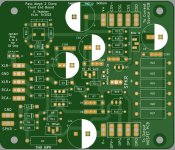
If you want to play around with the front-end board, your timing is perfect. Yesterday I updated an Aleph 2 front-end PCB that I did a couple of years ago for a DIY member's Rawson re-build. This new board has all of the enhancements built into the "Classic Aleph" boards in this thread https://www.diyaudio.com/community/...or-modern-ums-chassis-builders-thread.382316/, but in a front end only board. It has pots to adjust bias, AC gain, and offset, AC Gain test jumper, film bypass caps (optional), additonal rail caps, etc.
I'm getting some of these boards made to upgrade a Rawson F2 soon. If you want a pair they're yours for cost of shipping, or I can send some gerbers to you.
I also have a large stash of matched classic Harris/Fairchild SFP9610's if you're interested. Matched from a batch of 850. These are the ones Papa prefers in the IRFP9610 family. You could try to hunt down toshiba's for the LTP, too. That's a bit trickier, though.
https://www.diyaudio.com/community/threads/the-aleph-design-reloaded.267857/
CLC is fantastic. Consider adding an RC to the CLC. So CLCRC. Try that in the PSU modeling tool. Aim to shave ripple. Don't try to burn off too much voltage, you'll have HOT resistors at A2 current levels.
If you want to play around with the front-end board, your timing is perfect. Yesterday I updated an Aleph 2 front-end PCB that I did a couple of years ago for a DIY member's Rawson re-build. This new board has all of the enhancements built into the "Classic Aleph" boards in this thread https://www.diyaudio.com/community/...or-modern-ums-chassis-builders-thread.382316/, but in a front end only board. It has pots to adjust bias, AC gain, and offset, AC Gain test jumper, film bypass caps (optional), additonal rail caps, etc.
I'm getting some of these boards made to upgrade a Rawson F2 soon. If you want a pair they're yours for cost of shipping, or I can send some gerbers to you.
I also have a large stash of matched classic Harris/Fairchild SFP9610's if you're interested. Matched from a batch of 850. These are the ones Papa prefers in the IRFP9610 family. You could try to hunt down toshiba's for the LTP, too. That's a bit trickier, though.
Attachments

Thanks for your replies. Plenty to think about!
I will reply in more detail later when I can type on a normal keyboard rather than a mobile phone!
I will reply in more detail later when I can type on a normal keyboard rather than a mobile phone!
There were several discussions on this C9... I think it is correct to connect (-) C9 to Emitter Q5.I echo ZM's suggestion on this one:
https://www.diyaudio.com/community/threads/the-aleph-design-reloaded.267857/
CLC is fantastic. Consider adding an RC to the CLC. So CLCRC. Try that in the PSU modeling tool. Aim to shave ripple. Don't try to burn off too much voltage, you'll have HOT resistors at A2 current levels.
If you want to play around with the front-end board, your timing is perfect. Yesterday I updated an Aleph 2 front-end PCB that I did a couple of years ago for a DIY member's Rawson re-build. This new board has all of the enhancements built into the "Classic Aleph" boards in this thread https://www.diyaudio.com/community/...or-modern-ums-chassis-builders-thread.382316/, but in a front end only board. It has pots to adjust bias, AC gain, and offset, AC Gain test jumper, film bypass caps (optional), additonal rail caps, etc.
I'm getting some of these boards made to upgrade a Rawson F2 soon. If you want a pair they're yours for cost of shipping, or I can send some gerbers to you.
I also have a large stash of matched classic Harris/Fairchild SFP9610's if you're interested. Matched from a batch of 850. These are the ones Papa prefers in the IRFP9610 family. You could try to hunt down toshiba's for the LTP, too. That's a bit trickier, though.
Thanks for all your comments. I will reply to different issues in different messages to keep things
Heat
I realise the 4U 400mm enclosure does not have enough heatsink capacity to keep the 300W standard Aleph 2 output cool, let alone if I am going to lower the rail voltage without replacing the transformers. Having said that, I don;t want to buy new enclosures and would hate it if I had to change my amps to a smaller Aleph.
I remember that heatsink ratings are normally specified for 85 degrees C and a derating factor needs to be taken into account at a lower temperature (heat transfer is dependent on difference between heatsink and air temperature). The Conrad Heatsink website has some information about their heatsinks. Reading that it becomes clear that the 85 degrees often quoted is not absolute, but the rise above ambient!
https://www.conradheatsinks.com/technical-details.html#thermal
Conrad specifies their heatsinks ratings at 80 degrees above ambient and for 25 degrees above ambient a derating factor of about 1.4 is appropriate.

The Modushop 200x40x165 heatsink has an official rating of 0.38C/W. Modushop does not specify the temperature at which this applies, but lets assume it is the same 80 degrees C above ambient Conrad uses.
The 4U 400mm enclosure has 4 heatsinks, so effectively 0.38/4=0.095C/W. Taking a 1.4 derating factor into account, it comes to 0.133C/W. So, at 300W I can expect a 40 degree increase (which is only a bit less than I have found with my Aleph 2s).
I also remember that heatsink efficiency is greatly increased by airflow. An article I found on the Digikey website (https://www.digikey.com/Site/Global/Layouts/DownloadPdf.ashx?pdfUrl=F51974C9A6D544F1A7D8F119514B67FF) contains a graph that clearly shows the incresed efficiency at increasing airflow rates.

While this is just an example, it had got me thinking. Could this be an option?
Rather than a babysitter (as suggested by Zen Mod) under the amp, I am going to try increasing the airflow over the fins. I will mount ten 40mm fans underneath a 40x400mm aluminium strip and attach the strip underneath the fins.

Keeping the fan speed low (i.e. no noise) I still hope to create enough airflow to significantly increase the capacity of the heatsinks.
It will take me some time to work this out properly, but I think it is an option worth trying. If anyone else has attempted a similar approach, please let me know what your experiences were.
Heat
I realise the 4U 400mm enclosure does not have enough heatsink capacity to keep the 300W standard Aleph 2 output cool, let alone if I am going to lower the rail voltage without replacing the transformers. Having said that, I don;t want to buy new enclosures and would hate it if I had to change my amps to a smaller Aleph.
I remember that heatsink ratings are normally specified for 85 degrees C and a derating factor needs to be taken into account at a lower temperature (heat transfer is dependent on difference between heatsink and air temperature). The Conrad Heatsink website has some information about their heatsinks. Reading that it becomes clear that the 85 degrees often quoted is not absolute, but the rise above ambient!
https://www.conradheatsinks.com/technical-details.html#thermal
Conrad specifies their heatsinks ratings at 80 degrees above ambient and for 25 degrees above ambient a derating factor of about 1.4 is appropriate.
The Modushop 200x40x165 heatsink has an official rating of 0.38C/W. Modushop does not specify the temperature at which this applies, but lets assume it is the same 80 degrees C above ambient Conrad uses.
The 4U 400mm enclosure has 4 heatsinks, so effectively 0.38/4=0.095C/W. Taking a 1.4 derating factor into account, it comes to 0.133C/W. So, at 300W I can expect a 40 degree increase (which is only a bit less than I have found with my Aleph 2s).
I also remember that heatsink efficiency is greatly increased by airflow. An article I found on the Digikey website (https://www.digikey.com/Site/Global/Layouts/DownloadPdf.ashx?pdfUrl=F51974C9A6D544F1A7D8F119514B67FF) contains a graph that clearly shows the incresed efficiency at increasing airflow rates.
While this is just an example, it had got me thinking. Could this be an option?
Rather than a babysitter (as suggested by Zen Mod) under the amp, I am going to try increasing the airflow over the fins. I will mount ten 40mm fans underneath a 40x400mm aluminium strip and attach the strip underneath the fins.
Keeping the fan speed low (i.e. no noise) I still hope to create enough airflow to significantly increase the capacity of the heatsinks.
It will take me some time to work this out properly, but I think it is an option worth trying. If anyone else has attempted a similar approach, please let me know what your experiences were.
Front end
@rhthatcher Thanks for your very kind offer! I had recently looked at the pdfs in the "Classic Aleph Amplifier for Modern UMS Chassis Builder's Thread" (great by the way!) and was a bit jealous of the neat way you incorporated adjustment of DC offset, AC gain and bias current in those boards. Not to speak of the improvements (e.g. cap across zener).
I had to replace leaking psu caps on my Aleph P1.7 preamp and psu boards recently (also built by my late friend using KK boards at the same time, around 2006) and had some issues with one track lifting on the amp board. I was able to fix it, but a fresh board will be so easy to work on! I will send you a PM with my email address.
I have discovered that some parts my friend used in both the Aleph 2s and P1.7 were not great (e.g. the leaking cheap Chinese capacitors in my P1.7 and the cement resistors in the 2s), so I have no idea if the 9610s were properly matched (I can see on some photos that they are International Rectifier parts, marked 444P 1B 09, so I assume from the same batch at least). Your perfectly matched Harris/Fairchild 9610s are very tempting haha! Expect a PM soon 🙂
I bought 50 IRFP044N years ago, but have never got around to matching them (I haven't learned to match mosfets yet). They are in their original plastic strips (yellowed by age), so I assume they are from the same batch. If I get some really close matches I may consider replacing the output mosfets, assuming at their lower max. 55V drain-to-source voltage the 044s can be used in this amp. I don't which parts my friend installed and the way they are mounted (between the pcb and the heatsink) I can't even see them to check without dismantling the amp.
I assume if I check the resistance of the source resistors and check the voltage drop when the amp is warm, it should give me an indication if they were properly matched. Also, when I replace the resistors I will have to remove the boards from the heatsinks anyway. I think I will need to learn about matching and check the matching of the ones that are installed.
With respect to the caps to use in the front end I will refer to them using the original service manual part numbers.
C5: I assume it would be best to use a bipolar for C5 (IN- circuit)? Would a Muse bipolar ES be better than a Silmic II, Nichion FG or KZ?
C9 and C10: If I read the schematic correctly, the top of the caps would be at a higher potential than the bottom, so a polar rather than bipolar seems more appropriate intuitively. Do I read the schematic correctly? Is there a preference? I am not at the stage yet in my learning that I can determine the potential across the cap, so don't know what voltage rating would be appropriate. Can someone enlighten me?
@Zen Mod I only have 220nF MKC. Worth using one for each electrolytic, or do I need to add a few at each cap?
Power supply
@TungstenAudio Thanks for the tips. I think the quality of the caps my late friend used are not the issue (they are big F&T 47000uF 63V cans).

What worries me is that psu designer predicts a ripple of -3 to +23A! At a ripple rating of 13.2A this seems much too high.

@rhthatcher Because my transformer is rated at 2 x 40V, my rail voltage is too high (psu designer predicts 51V). It is for that reason that I am trying to drop 5V with added resistance in the psu. According to psu designer, the ripple at the load (constant 17R load) is only 10mV, so I assume it is not really an issue. Going to RCLC only improves this marginally.
If I add 0R75 before the first C, the ripple seen by the first cap drops from 26A to 13A (within spec of the cap). I also drop my rails to about 45V, which is where I would like them to be. If I do decide to try this setup, I will use two 100W 1R5 in parallel for each rail. They will have to handle about 13W each, so should be fine. It is just the extra heat that will be a problem haha. But for that I have a cunning plan (see previous post).
Some years ago I bought Panasonic 15000uF/63V (snap-ins; not sure of the series without checking) and NOS United Chemicon 33000uF/50V G32 series (large blue caps) from ApexJr that haven't been used yet. I can add these to C2 if required to drop the rail ripple even further. Assuming I have enough space in the enclosure.
I am worried that the coils in the CLC psu will generate fields that may be picked up by the amp circuits. Is it possible (assuming I have the space) to enclose these in steel boxes?
Enclosing the transformer in a steel box is something I am also looking at, but I need to open the amps first to see what room I have to play with.
@TungstenAudio Thanks for the tips. I think the quality of the caps my late friend used are not the issue (they are big F&T 47000uF 63V cans).
What worries me is that psu designer predicts a ripple of -3 to +23A! At a ripple rating of 13.2A this seems much too high.
@rhthatcher Because my transformer is rated at 2 x 40V, my rail voltage is too high (psu designer predicts 51V). It is for that reason that I am trying to drop 5V with added resistance in the psu. According to psu designer, the ripple at the load (constant 17R load) is only 10mV, so I assume it is not really an issue. Going to RCLC only improves this marginally.
If I add 0R75 before the first C, the ripple seen by the first cap drops from 26A to 13A (within spec of the cap). I also drop my rails to about 45V, which is where I would like them to be. If I do decide to try this setup, I will use two 100W 1R5 in parallel for each rail. They will have to handle about 13W each, so should be fine. It is just the extra heat that will be a problem haha. But for that I have a cunning plan (see previous post).
Some years ago I bought Panasonic 15000uF/63V (snap-ins; not sure of the series without checking) and NOS United Chemicon 33000uF/50V G32 series (large blue caps) from ApexJr that haven't been used yet. I can add these to C2 if required to drop the rail ripple even further. Assuming I have enough space in the enclosure.
I am worried that the coils in the CLC psu will generate fields that may be picked up by the amp circuits. Is it possible (assuming I have the space) to enclose these in steel boxes?
Enclosing the transformer in a steel box is something I am also looking at, but I need to open the amps first to see what room I have to play with.
@Zen Mod I only have 220nF MKC. Worth using one for each electrolytic, or do I need to add a few at each cap?
one is enough
it just happens that I learned from Pa - when you find interesting part and you can buy it in quantity, you'll find many places where to put it
so, I'm buying Philips 1uF/100V MKC in 1K quantity, whenever I'm down to 50
I would take Randy up on his offer for the boards. The harris parts are very nice too. I have used them in a few amplifiers.
With the cases you have, you may want to lower the voltage further down than the Aleph 2 spec. An Aleph 60 is 25v secondaries. an Aleph 2 is 37v secondaries. So using your estimated heat dissipation, figure out what you can get away with.
Transformers are not that expensive in the grand scheme of the whole project. At least Anteks are not that expensive. With lower voltage and bias than a stock Aleph 2, you can use say a 500va transformer per monoblock as opposed to a 600va+
I recently discovered why my Aleph J was sounding dark and nowhere as good as my factory Aleph 3. It turned out the caps in my psu (33000uF/50V Nippon Chemi Con) were responsible, and simply adding an old 15000uF/63V Panasonic T-HA to each rail made a huge difference.
My Aleph 2 psu currently has 4 x F&T 47000uF/63V GM caps per monoblock. For as far as I can make out on photos they are marked "40/085/56 T 9". I can't find info to read the code. Does anyone know what the age could be? They were bought new in 2006 but it is unknown the dealer (not a big distributor like Mouser) had them on the shelf.
Has anyone used F&T GM caps in their poweramps before? Worth replacing?
Your thoughts are appreciated.
Last edited:
for my knowledge, F&T are good brand
now, date code - rings as 1985, but far from me being sure of it
if you search for datasheet, maybe you'll find more info about datacode
now, date code - rings as 1985, but far from me being sure of it
if you search for datasheet, maybe you'll find more info about datacode
I can't find anything in the datasheet/catalog or online. I think this will have to wait until I do the other mods and see what it sounds like then, before deciding.
it's simple as this
if there is no hum and you're happy with bass - they're not "dry"
if you connect (temporary, but in proper way and with shortest wires possible) set of 50uF motor runs, and you don't hear substantial difference in highs, they're having decent low ESR on higher F
ZM boasting - I still have 10 or so Philips 47mF/25Vdc caps, having printed on them claim of 10A++ ripple current @ 20KHz; go figure - I don't care when these are made, I know they must be good whenever I'm going to put them in use
set of these (2+2) are singing in my own SissySIT; sadly or not, no space for motor runs in case
The amps haven't been switched on for a while but I am pretty sure there was no hum, so if that is still the case I will assume the large caps are not dry.
I have a battery tester that I also use to test resistance of low Ohm resistors. It supposedly tests at 1kHz and I bought it to test Lithium battery cells.
https://a.aliexpress.com/_mrO60mc
I'll measure some new caps and see if the measurements are within the expected range. I can then try it on some spare old 33000uF/50V Nippon Chemi Con and 15000uF/63V Panasonic T-Ha that I bought from ApexJr and have had in my cupboard for at least 10-12 years. It will be interesting to see how they measure.
The Aleph 2 psu is CLC with one big 47000uF cans in each C.
I have some low impedance United Chemicon KYB (2200uF/63V) as well as some 4.7uF polypropylenes. It may be worth adding both to the final C.
I just tested 8 old but never used Panasonic 15000uF/63 T-HA caps (date code 9352C3).
Max. ESR according to datasheet is 27mOhm at 120Hz and 23mOhm at 20kHz.
My tester is supposed to work at 1kHz, so max according to will be somewhere 23-27mOhm.
All measure 13.xxxmOhm, so I assume they have passed the test.
My multimeters cannot handle 15000uF, so I either need a new multimeter or an LCR meter.
Thanks for all your comments. I will reply to different issues in different messages to keep things
Heat
While this is just an example, it had got me thinking. Could this be an option?
Rather than a babysitter (as suggested by Zen Mod) under the amp, I am going to try increasing the airflow over the fins. I will mount ten 40mm fans underneath a 40x400mm aluminium strip and attach the strip underneath the fins.
View attachment 1211204
Keeping the fan speed low (i.e. no noise) I still hope to create enough airflow to significantly increase the capacity of the heatsinks.
It will take me some time to work this out properly, but I think it is an option worth trying. If anyone else has attempted a similar approach, please let me know what your experiences were.
Good timing seeing this.
Turns out my super duper XA252 SIT, aka Macho SIT, immolated its right channel when I put it in the rack... the A2s have done fine on the same shelves but Mr. Macho didn't like it... "Dad do you smell smoke?"...
Turns out the issue was not with the stuff mounted on the heat sinks but the internal cavity overheating and taking out some components... even though they had their own little heatsinks... cooling into the cavity.
(Mea culpa... some people burn electronics, I smoke them... ).
So, now I'm addressing this. I ordered top and bottom plates from Gianluca with additional cooling slots and I may have a local machine shop build me fully perforated top and bottom plates like the ones you see on a tube amp cage. I'm also increasing the distance between shelves on the rack.
But, I'm also building a babysitter.
Right now, I got a Vantec Stealth 12v fan that I build on a plate eons ago to cool the components in a credenza system. It works quite well, it is very quiet... so the plan is to make it so that it cools just the internal cavity of the amp and leave the main heat sinks out in the open. About 15 inches wide, just enough to direct air into the slots of the bottom cover.
However, if I extend the babysitter to cover the bottom side of the heatsinks as well, it may also direct airflow over them. IF I do this, I might use two or three fans.
I do have one question... in order to optimize the flow into the cavity, I need to provide some means of sealing the airflow... I'm concern that weather stripping might melt and make a mess if it comes into contact with the hot chassis.
Also, I don't plan on having a thermo switch. I used to run a similar set up on top of the tube cages of my tube amps years ago and I got into the habit of turning them on/off with a lighted switch on the front panel of that "extractor babysitter". You just can't miss it then.
Any ideas?
Not sure if you want to do any sealing. In computers they use fans and direct airflow/extraction where it is needed, sometimes using elaborate plastic funnel chaped things on the cpu cooler to direct the heat out of the enclosure. I would look for something like that, to optimise the airflow you are generating with a fan, rather than sealing.
If you do want to seal, why not seal with solder?
If you do want to seal, why not seal with solder?
- Home
- Amplifiers
- Pass Labs
- Aleph 2: plans to modify a 17 year old diy build