Ive started building even though I havent ordered semis etc, but i have a wee issue.
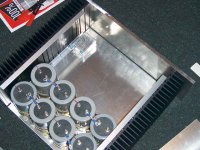
The caps I have are a little large, they are 15mm (just over half inch) away from the sinks. Will I have enough room to mount the boards and FETs or will the bourds touch the caps. If I can squeeze it in, will the heat damage my caps. I had an idea of using a tin copper foil as a jacket around the caps to maybe keep them cool?
Second question is , I have found some surplus line filters, they are siemens 10 amp rating. Should the thermistor go at teh input end or load end or does it not really matter? Should I use them and are there any benefits?
I also see that Nelson uses a thermistor to ground on the earth.
Is this important? I dont understand because if current flows then their will be a volt drop and not true earth. Would this be negligible?
Attachments
I haven't built this yet, so I'm not a true expert, but I have built things, and I have done lots (too much) of reading about it, so here's my opinion.
1. I don't think that you will have enough room for mounting boards and FETs between the caps and sinks as you have them. Consider arranging your caps as 3x3 instead, leaving a corner open with a cap missing. 8 caps total. Then move them away from the sinks, and that will leave a 'corner' to mount your transformer. So it won't be symmetrical. That's not important except for esthetics. I think that then the heat won't be an issue for the caps, as long as you get the caps 30mm or so away from the sinks.
2. I believe the thermister should go downstream of any line filter you have. I really can't comment on whether the line filters are beneficial or correct rating for the amp.
3. The thermister between power ground and signal ground keeps the two separate to reduce ground loop effects until there is a short somewhere, in which case it conducts, the resistance rapidly drops, and the fuse blows. Keep in mind, it's a negative temp coefficient thermistor. Resistance is high and goes low with increasing temperature.
4. Additionally, I'm not sure you have enough heatsinking. I'm guessing that your sinks are somewhere about 750 sq. in. each if you have 30 fins of 1.75 in by 7 in. high. I built one channel of a Zen 3 and using a sink of about 575 sq. in. I got about 65 deg. C while dissipating about 80W. So for one zen channel I should use a sink about the size of the one you have to get the temperature down to 50-55C. So maybe you can dissipate 160W with the two sinks which is about half of what you need to do. It's not a bad idea to concentrate on the circuit first, kluging it up on a piece of plywood with the sinks to see what kind of temperature rise you get before you commit to a given chassis.
5. It looks like you're planning to run those caps in series. If they are each rated for 50V or more, you don't want to do that. Run them in parallel.
6. If you're committed to that chassis and those sinks, consider building a mono Aleph 5 or maybe an Aleph 60.
Is this a chassis for stereo Aleph2?
What is the value of the caps?
How many transformers and how big?
What is the value of the caps?
How many transformers and how big?
Hi Vpharris and Peter,
I havent even considered moving it round so its non symmetrical, aethestics matter😉 but I may have too. I do have another issue, Im using a 1kva Toroidal which will take up a considerable amount of space. The transformers are 160 mm in dia.
This chassis BTW is for one channel, each sink is 160mm high X 340 long fins are 60mm. Total of 4 of these, 2 for each of my two chassis. The caps are 35V 100000uF each so yes Im parraleling them, each pair giving 50000uF and 70V. Total is 100000uF per rail in each amp, I guess I could half it and maybe find a couple of smaller caps?
I expect it will run at about 60 degrees as its dimensions are fairly immilar to Marijans amp. I also have a 10mm fromt panel, and will have vents punched in the lid down each side just over the fets, which should help cooling?
You mean the caps in series. 2 100mf make than 50mF.
It looks like you will have some space problems. Even thought the box should be very big according to what you said, the caps don´r leave much space in there.
I don´t think you will have enough space for the FETs on the sides.
The thermistor to ground is used to prevent current and so prevent ground loops. In case of a short it´s resistance goes down making the fuse blow.
Hi Promitheus,
Yes bit of a waste of farrads huh? Maybe I should start over again with the caps. It was hard work getting 16 of these babies and a big dissapointment really.
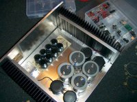
I have 8 15000uF @75Vcaps and I have 2 boards that hold 8 12000uF @50V. Was going to use these but Im not sure if its a bit to close to my rail voltage?
The small black caps in the pic are only 15000uF so total capacitance per rail will be 65000uF if I used 4 grey and 4 black.
Or could chance it with the 50V ones and place circuit board over the toroidal. Other thing is they are general purpose and not computer grade, (nippon chemi-con sme series).
what to do😕
Yes bit of a waste of farrads huh? Maybe I should start over again with the caps. It was hard work getting 16 of these babies and a big dissapointment really.
I have 8 15000uF @75Vcaps and I have 2 boards that hold 8 12000uF @50V. Was going to use these but Im not sure if its a bit to close to my rail voltage?
The small black caps in the pic are only 15000uF so total capacitance per rail will be 65000uF if I used 4 grey and 4 black.
Or could chance it with the 50V ones and place circuit board over the toroidal. Other thing is they are general purpose and not computer grade, (nippon chemi-con sme series).
what to do😕

What are inside the measurements for the chassis:
D 360mm X H 160 mm X W ???mm
What is the diameter of these big grey caps?
What is the height of 160 mm diameter toroid ?
May be we can still fit all parts nicely
argo
D 360mm X H 160 mm X W ???mm
What is the diameter of these big grey caps?
What is the height of 160 mm diameter toroid ?
May be we can still fit all parts nicely
argo
Hi Argo,
Inside diameter of case is 340 wide X 395 deep. The case is 160 high. Transformer is 160 dia and height is 75mm.
With metal clamps , the caps are 80mm dia 115 high.
Just had a thought while I was measuring the caps, the clamps add about 4 mm to the dia. thats an additional 8mm per side for 4 caps. Thing is they are designed to have a rubber sleeve which I havent got so I have packed them out with felt. But even with smaller clams I would only gain 2mm so its still a bit tight.
I think its too early to tell till I actually start assembling. Transformers are on the way I believe and its about time I ordered my semis boards etc.
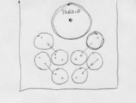
The solution is quite simple. By positioning caps this way you will gain more space. If this is not enough get rid of clamps and use silicone to glue them to a board which can be bolted to cassis. This is actually better, because the bottom of chassis will become quite hot and through the clamps the heat will be transfered to the caps.
Attachments
Yes bit of a waste of farrads huh? Maybe I should start over again with the caps. It was hard work getting 16 of these babies and a big dissapointment really.
You could move the transformers and some of the capacitors into a separate chassis and then have your remaining capacitors in the main chassis with the output devices and input.
I know you mentioned in another post that aesthetics matter a great deal for you, so I don't know how you'd feel about having another chassis beside each of your proposed monoblocks.
Erik
One time I had also some space problems with my amp because I used to many small caps. 28 electrolytic caps. I put the big toroid on the front not laying flat but vertical. I put the amp pcbs on the heatsinks. All this saves a lot of space. You just need a good metal essembly that can hold it. I used a thick metal angle I fastened to the bottom and then screwed the toroid on the angle. I let the toroid touch the bottom of the case so not to put so much strain on the angle.
Peter,
thanks for the sketch, I read your reply at work and thought why didnt I think of that, I like this forum.
unfortunately theses clamps are real pigs and couldnt get it to work so well. The clamps have 2 tabs on the side with screws, they are 2 u shapes, very difficult sods.
I am however warming to your plan B🙂
Will silicone really hold them in place? Think its my best option, and gives using your proposed layout, should fit comfortably.
Elarson,
Have my partners blessing for now, introducing another case might rock the boat, but I hear u 😉
I thought of using Nelsons regulator circuit from Zen4 and a completely separate chassis for both amps. I can still get more of the sinks and they are quite cheap.
Promitheus,
I would really like to mount the transformer vertically but it is exactly the same height as the case.
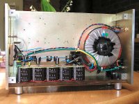
Im actually going to mount the pcb on the rear panel, I have loads of space for everything there, I thought about maunting 4 inputs as well, 2 x RCA and 2 x XLR, this way I can Bi amp in the future should I decide to. Apart from that theres just the fuse and input.
thanks for all your ideas guys🙂
thanks for the sketch, I read your reply at work and thought why didnt I think of that, I like this forum.
unfortunately theses clamps are real pigs and couldnt get it to work so well. The clamps have 2 tabs on the side with screws, they are 2 u shapes, very difficult sods.
I am however warming to your plan B🙂
Will silicone really hold them in place? Think its my best option, and gives using your proposed layout, should fit comfortably.
Elarson,
Have my partners blessing for now, introducing another case might rock the boat, but I hear u 😉
I thought of using Nelsons regulator circuit from Zen4 and a completely separate chassis for both amps. I can still get more of the sinks and they are quite cheap.
Promitheus,
I would really like to mount the transformer vertically but it is exactly the same height as the case.
Im actually going to mount the pcb on the rear panel, I have loads of space for everything there, I thought about maunting 4 inputs as well, 2 x RCA and 2 x XLR, this way I can Bi amp in the future should I decide to. Apart from that theres just the fuse and input.
thanks for all your ideas guys🙂
Won't mounting the caps like that prevent the proverbial magic smoke from escaping in the event of overheating?
Erik
Erik
I'll Give the silicon a try.
just making my order from digikey, they are so cheap compared to prices local. Ive been quoted about $4.50 for irfp240 and digikey sells them 1.49 for 100 lots.
Im planning on using 25 amp bridge rectifiers, not sure on voltage as they are surplus. Think they will be ok? Guess its not a big deal if they blow. Also ordering PCBs from Kristian.
Think Ill stick to general parts and try upgrading stuff later when Im familliar with the sound and better able to do comparisons. Still a bit cynical about the value of boutique parts. But think my DIY education would be incomplete without flirting with exotic parts😉
Use a separate rectifier per rail. And don't glue caps directly to the bottom of the metal chassis, but use some sort of a sub-plate, preferrably of material which doesn't transfer heat well.
- Status
- Not open for further replies.
- Home
- Amplifiers
- Pass Labs
- Aleph 2 construction issues