folkeb said:I have put about 1,5 ohm power resistors in series after the rectifier bridge before the caps to bring down the voltage.
Did you measure the voltage drop across the 1R5 resistor?
Can you tell us the measured value?
Detach the bridge rectifier away from the aluminium plate, and
sense whether the bridge is getting hot or the aluminium.
Zen Mod said:
looking at
http://i40.photobucket.com/albums/e217/folkeb/Aleph/DSC_0128.jpg
xformers are mounted properly
?!?
Sorry, I assumed this was just a mockup. I imagined the toriods mounted on the floor of the chassis and the al plate was then mounted close to the top of the toriods AND I thought the mounting bolt may have be touching the chassis and the al plate which would also be earthed. 😕
I've taken some pictures that so the actual test setup. I will place the top alu plate next to the bottom one and see what happens. I may be able to find the heatsource this way.
http://i40.photobucket.com/albums/e217/folkeb/Aleph/DSC_0148.jpg
http://i40.photobucket.com/albums/e217/folkeb/Aleph/DSC_0149.jpg
Thanks for all the help
http://i40.photobucket.com/albums/e217/folkeb/Aleph/DSC_0148.jpg
http://i40.photobucket.com/albums/e217/folkeb/Aleph/DSC_0149.jpg
Thanks for all the help
The toroid has a rubber mat under and on top of the toroid. On top of the top mat there is a metal plate that bolt goes through. The bolt functions as a thermal connector between the two alu plates.
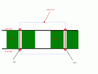
if central bolts through each xformer are electrical conductive between two alu plates ( and they are,according to quote) than you can't have any other electrical contact between plates because that will make short turn in secondaries of xformers;
xformers are enough huge that this short can't be cause for their too much heating,but this turn short can influence local heating on plates-exactly in spots where short is maked......
I'm clear enough?
think about solder gun and how it works-tiny wire is hottest part of it,incidentally 😉
edit:
looking again at http://i40.photobucket.com/albums/e217/folkeb/Aleph/DSC_0149.jpg
I think that both rods through TWO xformers are MORE THAN enough for short circuit ;
for test- pull out one rod ,and test for heating.if that is case0isolate both rods from at least one plate-they even don't have enough temp transfer capability for "transferring heat between plates"
The amp plays music!! However, I took the top off and put besides the bottom plate. This removed the heat at once. So it must be something to do with the plate sitting on top of the trannies and being electrically connected. Will try to find a good solution for this and see what happens. Apart from this, what resistors (wattage) would you deem safe to use? I blew the 15w 1,5ohms, it fell apart and burned!! I want to bring the voltage down by 6 or 7 volts. Isn't this 7*4 = 28? Would I need 50 w or should I parallel to 25?
folkeb said:The amp plays music!! However, I took the top off and put besides the bottom plate. This removed the heat at once. So it must be something to do with the plate sitting on top of the trannies and being electrically connected. Will try to find a good solution for this and see what happens. Apart from this, what resistors (wattage) would you deem safe to use? I blew the 15w 1,5ohms, it fell apart and burned!! I want to bring the voltage down by 6 or 7 volts. Isn't this 7*4 = 28? Would I need 50 w or should I parallel to 25?
your desired voltage difference on resistor is exactly U=RI
I dunno,and I'm lazy now to look,how much of current you put through resistors,but burned power in resistor is exactly P=I^2 x R
when you calculate burned power in resistor,scale it at least twice-say -if you have dissipation of 12W,then use 25W resistor,etc....
I told you-try without resistor and look where you'll finish with voltage across caps....
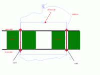
little sketch of your (probably ) short circuit is enclosed ;
if that is the case-insulate rods from plates or leave rods out and use several smaller rods not placed through donut cores,but around them
Attachments
I have to say that I should listen more to good advice. I have now successfully started up the Aleph 1.2 with 59 volts on the rails and 229 on the variac. This is with just one resistor of 0,3 ohms. To be on the safe side I will use another in series and se if this brings me within limits. I measured 59.7v with 230 on the variac. The mains are 231 today so I should probably have a volt or two less.
With regard to softstart this issue is long gone. One thermistor CL-10 did the trick. I have just got the 10 CL-10s that I ordered. Anyhow, no problems with the fuse blowing. Just wonderful!! That is one CL-10 handles 1250VA and 528000uF.
With regard to the strange heat development I will try to isolate the metal rods electrically from the bottom plate by using heatshrinks (lots of them in layers. Do you think this will help?
The sound seems very good so far. Difficult to say absolutely, but it is very promising.
I measured from 11mV to 20mV DC, with cables all over the place.
The heatsinks weren't very hot either after 30 min playing. They were warm, but not hot. I would guess 40 - 50 degrees. Not bad!!
😀
folkeb said:
With regard to the strange heat development I will try to isolate the metal rods electrically from the bottom plate by using heatshrinks (lots of them in layers. Do you think this will help?
😀
use 4 rods (instead 2) around xformers,not through them
in that case- they don't need to be isolated
If it only was that simple. Unfortunately the capacitor board is packed and there is no way that I can fit to rods. I took the bolts out and it is clear that they have had some energy going through them, the metal had a discoloring in the middle lengthwize- not good!! The rubber mats were slightly burned-this explains the smell we experienced - not good either!!
Based on the drawing I decided to try and isolate the bolts. So I isolated the lower part of the bolts from the bottom plate as this will prevent the loop you drew Zen Mod. As isolators I used 2 layers of heatshrink and a rubber ring between the bolt head and bottom plate. (The rubber ring is to prevent the metal to cut into the heatshrink as the bolt head is pressed agains the bottom plate). I used an additional rubber mat on top of the metal holding part of the transformer (the round disk that the bolt goes through that holds the transfomer in place - sort of a disk with a shape that fits into the top part of the hole in the transformer)
I put on some power and adjusted it up to about 50v on each rail and waited for ten minutes, constantly checking for temperature rise or any thing other out of place. Nothing.... It seems as isolating the bolts did the trick. Now I have to figure out two independent ways of isolating the bolts. I like to have two barriers to be on the safe side of things!
Does this confirm what happened, or does it shed new light on the incident?
This project is so much more enjoyable as I now know that it will work in the end!
folkeb said:
Does this confirm what happened, or does it shed new light on the incident?
yup-both 😉
This project is so much more enjoyable as I now know that it will work in the end!
I'm glad for that- in real DIY spirit - you do it primary for funnnnnnnnnn
ps-you can use bakelite or plastik washers instead of rubber ones
Zen Mod / Folkeb,
I cannot understand why there is a leak/short in the way the transformers are mounted. Folkeb, I assume that the transformer are well insulated, if so then where is the leak coming from?
Is the transformer's electromagnetic forces somehow causing current to flow in the bolt and then into the boards resulting in a short? I want to understand the root cause of what is hapenning so that I do not repeat it with my 2x1000VA transformers which were going to be mounted in a similar fashion to Folkeb's.
jasonlky said:Zen Mod / Folkeb,
I cannot understand why there is a leak/short in the way the transformers are mounted. Folkeb, I assume that the transformer are well insulated, if so then where is the leak coming from?
Is the transformer's electromagnetic forces somehow causing current to flow in the bolt and then into the boards resulting in a short? I want to understand the root cause of what is hapenning so that I do not repeat it with my 2x1000VA transformers which were going to be mounted in a similar fashion to Folkeb's.
look at that little sketch few posts above,and imagine piece of wire where I draw blue "short circ " line
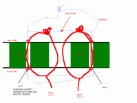
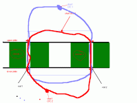
current path is closed through "first bolt-upper plate-second bolt-lower plate" route ,same as that you have one shorted turn in secondary winding ;in this case-via 2 xformers just because short turn is routed through both cores......
Zen Mod said:clearer?
Zen Mod,
Actually no.
I understand that it is a closed circuirt. But where does the current come from? Assuming all components are electrically isulated, there should not be any current flowing in the circuit as you have drawn ".... and you did not have to draw the wire to press on your point."
Here is my question.... are the transformers electromagnetic properties causing current to flow in the bolts? If this was already discussed and confirmed in a previous post, I apologise.
I don't really understand it myself, but I think it has something to do with the fact that the transformers induce a current in the bolt and that somehow there was a short. Is this correct?
yes-electromagnetically induced short circuit through bloody shorted turn through each core-same as you wound it with wire.....
look at pic bellow-I drew two paths,for each xformer one,but they are in fact one path ...
remember- first posts are just because not insulated bolts
look at pic bellow-I drew two paths,for each xformer one,but they are in fact one path ...
remember- first posts are just because not insulated bolts
Attachments
Zen Mod,
Thanks for the confirmation. This should go into some kind of Dos and Don'ts list!! Although I understood the principle, I just could not put 1 and 1 together.....
Folkeb, I assume that this bolt plays a structural purpose in holding the lower and upper plates in place. As such you'd need to insulate the bolt or search for a non conductive bolt, possibly plastic, from your local hardware shop. Use your imagination.
- Home
- Amplifiers
- Pass Labs
- Aleph 1.2 questions (soon done)


