Hi Folks,
Got Aleph 0 from a friend to overlook. Figured out it needs dc re-adjusting and rebiasing. For DC offset it is quite clear, the right pot does the thing. But I am feeling a bit lost with biasing. I understand the left pot is setting the bias, but what is the best way to measure? Points and values, if you don't hesitate.
Thanks in advance.
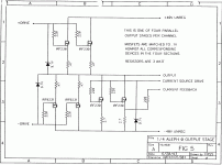
On the main board there are two pots, P1 for DC offset and P2 for output
stage bias. The attached image is 1 of 4 parallel sections that make up
the output stage, and is what you see on one vertical metal section of
the sinks.
The output stage is mainly biased by a constant current source which is
not adjustable. The top IRF230's have a .47 ohm Source resistor whose
voltage divided by .47 and multiplied by 8 shows the total bias current.
The IRFP9230 transistors also have .47 ohm resistors, and P2 should be
set so that the voltage is 1/5 the amount of the top .47 ohm resistors,
in other words the "pull" stage of IRF9230's is biased at 1/5 the current
of the whole output stage. When you adjust this, you must go back and
remeasure the voltage across the IRFP230 .47 ohm resistors, as the pot
adjusts this value a bit as well, and you want the 5:1 ratio.
Attachments
I'm afraid, it isn't that version you have, but maybe help:
very helpfhul, many thanks.
I have a hard time to remove the top cover from my Aleph 0 amps, mostly because I don't live on that island where imperial screws are a thing. I don't have the right imperial Allen tool for the small screws that hold the cover to the heat sinks. I tried using a Torx that fits in the screw head, but the Torx bit broke in the process. I decided to stop there.
Two questions:
(1) What is the size/dimension for the Allen tool? With a bit of luck I might be able to procure one here...
(2) There are two holes in the top cover, and there's a pot underneath each hole. I guess the idea is adjust things with a screwdriver through these holes, with the top cover on. Adjusting DC offset from by hooking up a DVM to the speaker terminals should be trivial, but what about the second adjustment? What do I measure, and where, without removing the top cover?
Ok, figured it out. Found the service manual with the instructions for adjustment. In short:
POT-1 adjusts DC offset at the speaker output. I shorted the XLR balanced inputs for 0 VDC input.
POT-2 adjusts the biasing of the OPS (you'll want 250 W-rms power consumption from the mains, which I measured using a current-sensing resistor inserted to the mains supply as described in the service manual).
No need to open the amp at all 🙂
- Home
- Amplifiers
- Pass Labs
- aleph 0 biasing