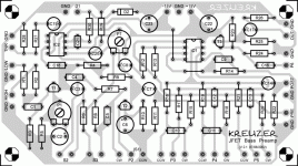
What are you wanting to try and simplify?, it's a simple enough little circuit, and he even gives you a nice easy PCB layout.
pre amp
i already made the board and completed all parts exept the wiring,any one who can give me idea of the actual wiring of pots and switches much welcome
.thanks
i already made the board and completed all parts exept the wiring,any one who can give me idea of the actual wiring of pots and switches much welcome
.thanks
Through some very simple deductive reasoning (I mean very simple) you should be able to easilly figure this out by simply looking at the schematic and at the PCB.....
Hint: The pots and switches are labeled on both the schematic and on the PCB....They are labeled P1,P2,P3 ect (For pots) and switches are S1,S2,S3 Ect, power supply should be easy to figure out.....
here"s another hint: CW and CCW means Clockwise and counter Clockwise .......
😀
Hint: The pots and switches are labeled on both the schematic and on the PCB....They are labeled P1,P2,P3 ect (For pots) and switches are S1,S2,S3 Ect, power supply should be easy to figure out.....
here"s another hint: CW and CCW means Clockwise and counter Clockwise .......
😀
How did you do it?
So do any of you people who actually finished this preamp know how to select the source resistors for the JFET's? Please see this tread:
http://www.diyaudio.com/forums/showthread.php?s=&threadid=114720
Thanks!
Eugenio
So do any of you people who actually finished this preamp know how to select the source resistors for the JFET's? Please see this tread:
http://www.diyaudio.com/forums/showthread.php?s=&threadid=114720
Thanks!
Eugenio
- Status
- Not open for further replies.
