Hi,still in the testing stage for the Alpha 20, a couple of questions please.
Both channels running from the same power supply of 23.5 volts,I am using 0.33ohm for R131 and 0.11ohm for R132 the voltage measured across R131 for one channel is 615mV, the other channel measures 580mV? is this a problem? Why the difference?
Also I am confused now about the size of C111 originally 1000uf, does this need to be lowered and does R111 need to be increased in value, or is this just for the 4 ohm version?
thanks for your patience.
regards
Alan
Alan,
R131 is the current set resistor and setting is Vce of the current transistor base to emitter divided by the the value, 0.33, should give you the current through that resistor.
615mV v. 580mV represents 1.86A v. 1.76A. This is close enough and tells you that the controlling transistors have wider tolerances, almost at ends of the spectrum. You could replace one of those transistors and almost definitely be sure to get a closer tolerance, bringing close to identical current.
BUT, it won't affect the amp otherwise!
Congratulations, you have two operating amplifiers.......!
Hugh
thanks Hugh / irribeo for the replies. The control transistor is V121 BC547 I presume?. The resistor is Panasonic ERX range they are 5%. So that is the two options to obtain closer matched currents?
is C111 still 1000uf for 8 ohm version?
regards
Alan.
is C111 still 1000uf for 8 ohm version?
regards
Alan.
Yes, Alan, 1000uF is correct for C111 and V121 is the BC5471, whose base and emitter are strapped across the 0.33R sense resistor.
Irribeo is correct too, if on of the resistors is up 5% and the other down, you have your 10% diff as well, so these tolerances are quite acceptable.
All this is only important when you are driving a 4R load, not with 8R as neither outputs will ever turn off.
Hugh
Irribeo is correct too, if on of the resistors is up 5% and the other down, you have your 10% diff as well, so these tolerances are quite acceptable.
All this is only important when you are driving a 4R load, not with 8R as neither outputs will ever turn off.
Hugh
Can you explain why the Panasonic is the best choice at 3W resistor as Mr. xr stated, why can't wirewound Dale lvr 5W used as I have those and a few csm series i think. Panasonic I have are 1W cheap blue ones.Yes, Alan, 1000uF is correct for C111 and V121 is the BC5471, whose base and emitter are strapped across the 0.33R sense resistor.
Irribeo is correct too, if on of the resistors is up 5% and the other down, you have your 10% diff as well, so these tolerances are quite acceptable.
All this is only important when you are driving a 4R load, not with 8R as neither outputs will ever turn off.
Hugh
To be clear you have 10R ground link resistor on pcb signal ground to the one point between smoothing caps I call it diamond, wiring node "
Connect near input sockets Ground Lift 10nF 1k parallel to E metalwork case, heatsink
The Alpha 20 board does not have built in 10R ground lift resistor on signal ground. What does putting 1k parallel 1nF between RCA signal ground and chassis do? Isn’t that a 1k ground lift and now a potential may be built on 1k very easily?
thanks Hugh / irribeo for the replies. The control transistor is V121 BC547 I presume?. The resistor is Panasonic ERX range they are 5%. So that is the two options to obtain closer matched currents?
is C111 still 1000uf for 8 ohm version?
regards
Alan.
It helps to match the Hfe of the Bc547 Aleph CCS transistor between left and right channels. I did this and got near identical bias currents (some was luck that ERX resistors all averaged out in the wash).
I don't know if this has been discussed previously for the ALPHA 20, but what min size CPU coolers does one need for each pair of devices (as per Vunce's setup)?
Hajj,
Alpha 20 doesn’t need CPU coolers as the heat load per MOSFET is moderate 35w (for 1.3amp) to maybe 50w (2amp bias) ea so if you prefer conventional heatsinks sized appropriately can work fine. But if you want to use CPU cooler, pick one with large pad so that you can cool two MOSFETs with one. The one Vunce used is a particularly large area perfect for this. Most heat pipe CPU coolers with fans are designed for heat loads of 100W+ and should be sufficient. On the Alpha BB, the heat load per MOSFET is about 100W so I have a dedicated CPU cooler for each. The other consideration is a large diameter (120mm) PWM (variable speed) fan to keep the noise to a minimum. Based on the research that Indid, the surplus Dell CPU cooler that Vunce and Juntuin have are the best route for this project if you want to use active cooling as they have large 75mm wide thermal pads and are inexpensive.
Alpha 20 doesn’t need CPU coolers as the heat load per MOSFET is moderate 35w (for 1.3amp) to maybe 50w (2amp bias) ea so if you prefer conventional heatsinks sized appropriately can work fine. But if you want to use CPU cooler, pick one with large pad so that you can cool two MOSFETs with one. The one Vunce used is a particularly large area perfect for this. Most heat pipe CPU coolers with fans are designed for heat loads of 100W+ and should be sufficient. On the Alpha BB, the heat load per MOSFET is about 100W so I have a dedicated CPU cooler for each. The other consideration is a large diameter (120mm) PWM (variable speed) fan to keep the noise to a minimum. Based on the research that Indid, the surplus Dell CPU cooler that Vunce and Juntuin have are the best route for this project if you want to use active cooling as they have large 75mm wide thermal pads and are inexpensive.
I meant 10nF 1k 0.5W ground lift. CorrectionThe Alpha 20 board does not have built in 10R ground lift resistor on signal ground. What does putting 1k parallel 1nF between RCA signal ground and chassis do? Isn’t that a 1k ground lift and now a potential may be built on 1k very easily?
I meant 10nF 1k 0.5W ground lift. Correction
And you find that a 1k resistor between RCA ground and chassis helps to reduce ground loop hum?
No. I said connect near input sockets. Reread near input sockets 10R ground link you know where to connect it don't you. Between the smoothing caps wiring node, some like t some square 45deg tilt diamondAnd you find that a 1k resistor between RCA ground and chassis helps to reduce ground loop hum?
You can twist positive negative if possible.
You maybe like thin earth wires, I don't definitely do not.
No. I said connect near input sockets. Reread near input sockets 10R ground pcb link you know where to connect it don't you. Between the smoothing caps wiring node, some like t some square 45deg tilt diamond
You can twist positive negative if possible.
You maybe like thin earth wires, I don't definitely do not.
Hajj,
Alpha 20 doesn’t need CPU coolers as the heat load per MOSFET is moderate 35w (for 1.3amp) to maybe 50w (2amp bias) ea so if you prefer conventional heatsinks sized appropriately can work fine. But if you want to use CPU cooler, pick one with large pad so that you can cool two MOSFETs with one. The one Vunce used is a particularly large area perfect for this. Most heat pipe CPU coolers with fans are designed for heat loads of 100W+ and should be sufficient. On the Alpha BB, the heat load per MOSFET is about 100W so I have a dedicated CPU cooler for each. The other consideration is a large diameter (120mm) PWM (variable speed) fan to keep the noise to a minimum. Based on the research that Indid, the surplus Dell CPU cooler that Vunce and Juntuin have are the best route for this project if you want to use active cooling as they have large 75mm wide thermal pads and are inexpensive.
Thanks for the clarification, I will try and find what model coolers and fans they are using.
I am tempted to go the active cooling route because VUNCE's build looks really neat, and since I will be shipping in my heatsinks, I might as well go for the CPU coolers.
There plenty around Vunce ebay or he already had them available. You can read the whole thread again or...Thanks for the clarification, I will try and find what model coolers and fans they are using.
I am tempted to go the active cooling route because VUNCE's build looks really neat, and since I will be shipping in my heatsinks, I might as well go for the CPU coolers.
Don't you guys have plenty of computer related cooling systems at home? Storage. Watercooling systems. Chiller. Cascade condenser.
Thanks for the clarification, I will try and find what model coolers and fans they are using.
I am tempted to go the active cooling route because VUNCE's build looks really neat, and since I will be shipping in my heatsinks, I might as well go for the CPU coolers.
Hi Nick,
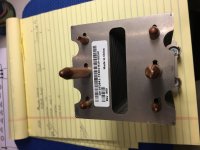
I got the Dell fd841 coolers from eBay.
But, There is two versions of them make sure you purchase the ones with 73304 in the model number. That’s the one that has the large copper mounting surface. Compare in the picture I’m attaching.
Attachments
Does this amp needs a linear power supply or does it work with SMPS also, especially the 20w version? Most of the builds looks to be using the linear power supplies here.
No. I said connect near input sockets. Reread near input sockets 10R ground link you know where to connect it don't you. Between the smoothing caps wiring node, some like t some square 45deg tilt diamond
You can twist positive negative if possible.
You maybe like thin earth wires, I don't definitely do not.
Perhaps you can provide a schematic or sketch because the way it is described in words, I see something else in my head.
Thanks.
- Home
- Amplifiers
- Solid State
- Aksa Lender P-MOS Hybrid Aleph (ALPHA) Amplifier