Hello friends.
Can you please give me the direction in this mic repair? When I connect the mic to the mixer (with phantom power) - I hear no sound from the amp.
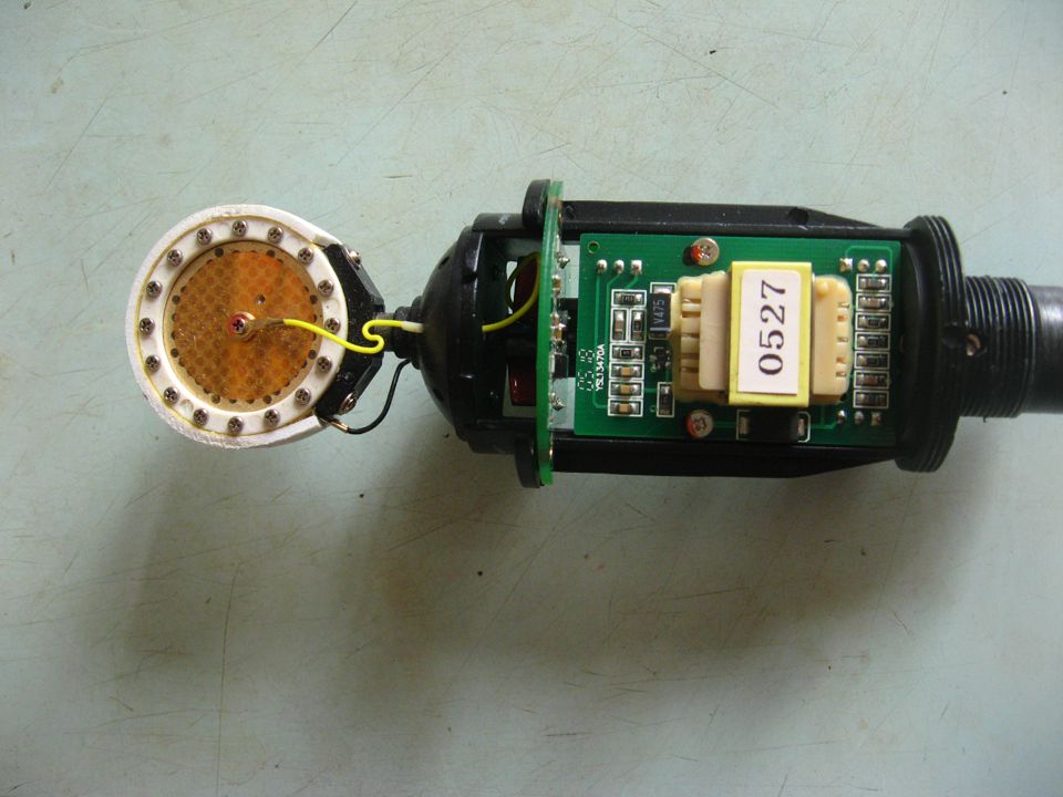
What is that capsule (what is the physics)?
When I watch the signal with oscilloscope (black wire of the capsule is ground, yellow – signal) after saying something into the capsule I see no voice frequencies but I see rise of the constant voltage (from zero to about 100mV). In this experiment the mic is disconnected from the mixer.

Can you please give me the direction in this mic repair? When I connect the mic to the mixer (with phantom power) - I hear no sound from the amp.
What is that capsule (what is the physics)?
When I watch the signal with oscilloscope (black wire of the capsule is ground, yellow – signal) after saying something into the capsule I see no voice frequencies but I see rise of the constant voltage (from zero to about 100mV). In this experiment the mic is disconnected from the mixer.
Attachments
First you start by measuring the current consumption of the microphone. Use a 48 volt power supply and two 6.8K resistors from positive to pins 2 & 3 and Pin 1 through a current meter to ground. The current should be between 1-2 milliamps.
There should also be a polarization voltage on the capsule. I don't think you will be able to see any signal voltage on the capsule.
To trouble shoot the electronics you disconnect the capsule and inject a signal (about 1 mV) through a coupling capacitor. Then you can follow the signal stage by stage to see where it stops.
Hello friends.
Can you please give me the direction in this mic repair? When I connect the mic to the mixer (with phantom power) - I hear no sound from the amp.
What is that capsule (what is the physics)?
When I watch the signal with oscilloscope (black wire of the capsule is ground, yellow – signal) after saying something into the capsule I see no voice frequencies but I see rise of the constant voltage (from zero to about 100mV). In this experiment the mic is disconnected from the mixer.
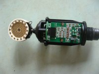
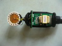
This is a classic large capsule externally polarized condenser mic, if you disconnect the preamp there is no power also the impedance levels are too high to debug with normal equipment. I would suggest you go to the micbuilders yahoo group to get help, there is a file section there with schematics of these types of mics and information on troubleshooting them.
Last edited:
If I had to repair a condenser microphone, I would first try to find a schematic, either from the manufacturer or from internet or from reverse engineering, and then check the bias point at any low-impedance nodes. Except for the high-voltage supply, its connection to the cartridge and the gate biasing circuit of the first FET, everything is usually low-ohmic enough to measure with a normal digital voltmeter, preferably connected through a 1 kohm series resistor to prevent any oscillations. You will need to apply phantom power to measure anything useful.
By the way, you can get some very funny effects when the biasing resistor of the gate of the first FET gets disconnected. For example, I once had to fix an AKG microphone that always worked fine when I tried to measure it, but failed after being connected to the mixing deck for more than half an hour. It simply took the gate of the input FET quite some time to drift to an unusable bias point.
By the way, you can get some very funny effects when the biasing resistor of the gate of the first FET gets disconnected. For example, I once had to fix an AKG microphone that always worked fine when I tried to measure it, but failed after being connected to the mixing deck for more than half an hour. It simply took the gate of the input FET quite some time to drift to an unusable bias point.
Last edited:
First you start by measuring the current consumption of the microphone. Use a 48 volt power supply and two 6.8K resistors from positive to pins 2 & 3 and Pin 1 through a current meter to ground. The current should be between 1-2 milliamps.
I connected the mic to the mixer and measured the current - it was exactly 1 mA.
I measured constant voltage on the capsule contacts - it was about 10mV. After the voice pressure to the capsule it raised to about 60mV and started to decrease at about 2mV per second to the initial value.There should also be a polarization voltage on the capsule. I don't think you will be able to see any signal voltage on the capsule.
To trouble shoot the electronics you disconnect the capsule and inject a signal (about 1 mV) through a coupling capacitor. Then you can follow the signal stage by stage to see where it stops.
I connected the output of the mp3 player to the input of mic preamp and heard nothing. I didn't try to trace the signal - I should find the schematic first.
I didn't find the schematicsI would suggest you go to the micbuilders yahoo group to get help, there is a file section there with schematics of these types of mics and information on troubleshooting them.
") but I wrote to the group.
but I wrote to the group.If I had to repair a condenser microphone, I would first try to find a schematic...
I'm trying...
Yeah, just recently encountered with similar leakage problem in a tube ampBy the way, you can get some very funny effects when the biasing resistor of the gate of the first FET gets disconnected. For example, I once had to fix an AKG microphone that always worked fine when I tried to measure it, but failed after being connected to the mixing deck for more than half an hour. It simply took the gate of the input FET quite some time to drift to an unusable bias point.
You should measure about 200V DC. The polarization voltage is missing, this is the problem.I measured constant voltage on the capsule contacts - it was about 10mV.
- Status
- This old topic is closed. If you want to reopen this topic, contact a moderator using the "Report Post" button.
- Home
- Source & Line
- Analog Line Level
- AKG Perception 100 mic repair