I am new member in this forum . Now, I got Power supply issue.
(1) headphone is added balance to unbalance transformer (600 ohm to 600 ohm,
Jensen input transformer ,model;JT-11P-1 ),so sound is more open and clear.
I also found more hum ,when I turn up volume.
(2) I mod the power supply . Headphone is supply 28 ~ 30 volt by BK 9110 power
supply or SL/Condor linear power supply model MB-28-1-A . I can get very good
sound and hum is gone. Well, I only can use 250 ohm (or upper impedance
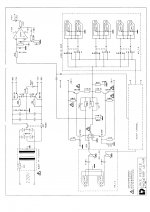
headphone like 600 ohm). The +/- 28 volt is directly connected the BD139 &
BD140 transistor ,please see attachment picture.
(3) If I connect with low impedance headphone (like Audeze LCD-2 ; 64 Ohm ) and I
can get normal sound around a second ,then I can only get very low sound . If I turn
up the volume ,I only get distortion sound .
(4) I try the change input transformer ( input 500 ohm ; output 50 ohm ) , The problem
is still there.
(5) When I disassembly the two 1000 uF capacitors ( not four 470 uF capacitors),
I get distortion sound for headphone 250 ohm .
I do NOT know how to do next step for my problem (My Audeze headphone ) Maybe,
capacitors are change to smaller uF capacitors ( eight 220 uF ? )
Any input is welcome .
(1) headphone is added balance to unbalance transformer (600 ohm to 600 ohm,
Jensen input transformer ,model;JT-11P-1 ),so sound is more open and clear.
I also found more hum ,when I turn up volume.
(2) I mod the power supply . Headphone is supply 28 ~ 30 volt by BK 9110 power
supply or SL/Condor linear power supply model MB-28-1-A . I can get very good
sound and hum is gone. Well, I only can use 250 ohm (or upper impedance
headphone like 600 ohm). The +/- 28 volt is directly connected the BD139 &
BD140 transistor ,please see attachment picture.
(3) If I connect with low impedance headphone (like Audeze LCD-2 ; 64 Ohm ) and I
can get normal sound around a second ,then I can only get very low sound . If I turn
up the volume ,I only get distortion sound .
(4) I try the change input transformer ( input 500 ohm ; output 50 ohm ) , The problem
is still there.
(5) When I disassembly the two 1000 uF capacitors ( not four 470 uF capacitors),
I get distortion sound for headphone 250 ohm .
I do NOT know how to do next step for my problem (My Audeze headphone ) Maybe,
capacitors are change to smaller uF capacitors ( eight 220 uF ? )
Any input is welcome .
Attachments
May be able to help .. re your item #'s:
1) The hum increase is VERY likely due to the stray magnetic field from the unit's power
transformer. Sure the Jensen is shielded, but no shield is 100%, and the amp has 60 dBV of gain. Proof: Leave the aux supply(s) running it, turn the original power switch on and off -- bet the hum goes off with the switch -- and a loud pop.
2) You didn't mention TWO power supplies. This circuit won't work correctly with the ground floating, with or without an input transformer. (Though having one probably saved you from a DC-latch situation that would have blown up some stuff, though.)
3) That's the exact symptom you get as the main filter caps discharge. The substitute power supply probably has 'current limit' set too low.
4) Forget the input transformer -- it has nothing to do with this distortion/output drive problem. Note that the Jensen catalog shows the JT-11P-1 to be 10K:10K, which is much better than 600:600 for this application.
5) Guessing that you meant 'disCONNECT the two 1000 uF capacitors' -- this would cause the
output to have no ground return AT ALL (AC or DC! -- instead of just none at DC). All assuming, as suspected earlier, that the auxiliary power supply is by itself, not paired with another.
Forget fiddling with different combinations of main filter caps. This circuit should have exceptional PSRR; those caps are not part of this problem.
You could give the input transformers their own private box, keeping it 15 or 20 cm away from the V6HP. Or find another use for them. The floating input they provide is absolutely heaven-sent in certain (usually professional) situations. But they are not designed to provide any sort of 'sonic enhancement'.
Regards,
--Rick
Hi Rick,
Thanks for your advices.
(2) When I use liner power supply , I will dis-connect original power supply
on board.
Leica chi
Thanks for your advices.
(2) When I use liner power supply , I will dis-connect original power supply
on board.
Leica chi
Hi leica chi,
You're very welcome. But .. umm-mm .. And I see now that I didn't explain myself very well in #2:
>> You will need TWO SEPARATE AUXILIARY supplies to operate this circuit.(*1)
I'm still a little fuzzy as to whether you have 2 linear supplies or not. I looked up the #'s of the two models you mentioned, and both are Single Output supplies. The V6HP can't work properly without a solid ground mid-way between the 30 volt rails. A single 30V supply connected across the Collectors of the BD139 and 140 won't do it. On top of that, those transistors serve ONLY the 741 IC, which only detects clipping!
Also, you can leave the original supply connected -- the bridge rectifier isolates the transformer -- but DO turn off the power switch, or unplug it: If power is applied to the transformer you'll be right back in the old boat with the hum problem.
Regards,
--Rick
*1) There are circuits that can provide a 'Virtual Ground', but that would be a heck of a lot of trouble to go to (and yield poorer quality sound) when a center-tapped line transformer will do better.
Hi Rick,
I tried two power supply to connect +/- 28 , +/- 15 volt. It can not fix my problem .
For your memtion:
>
The V6HP can't work properly without a solid ground mid-way between the 30 volt rails
>
How can I get solid ground for this situation ?
Thanks for your input .
Leica chi
I tried two power supply to connect +/- 28 , +/- 15 volt. It can not fix my problem .
For your memtion:
>
The V6HP can't work properly without a solid ground mid-way between the 30 volt rails
>
How can I get solid ground for this situation ?
Thanks for your input .
Leica chi
Hi Leica chi,
Would it be possible for you to show me on your original schematic, just where you've connected the auxiliary power supplies? Maybe mark it up in PBrush or equivalent?
It would help me grasp where we're overlooking something.
Thanks,
-- Rick
Would it be possible for you to show me on your original schematic, just where you've connected the auxiliary power supplies? Maybe mark it up in PBrush or equivalent?
It would help me grasp where we're overlooking something.
Thanks,
-- Rick
Hi Rick,
I only connect +/- 28 volt to BD139 and BD140 ,no more anything else .
Thanks for your input.
Leica Chi
I only connect +/- 28 volt to BD139 and BD140 ,no more anything else .
Thanks for your input.
Leica Chi
This plan can put 10 WATTS into 30 Ohms. (But not for long...)
The fact it will not play strong (ear-burning LOUD) says something is very wrong.
For instance: if the (un-protected!) power transistors are burnt-out, the TL071 "can" put audible power through the 1K to high impedance phones, but this will be very weak in low impedance phones.
More info needed. Can you use a volt-meter?
Attachments
Last edited:
Hi PRR,
Thanks for your help,
When I connect with B&K 9110 power supply , the meter setting:
+/- 28 volt , current limit :0.5 A , but actually meter show :
0.01 ~ 0.005 A for really time output !
I can not get more current for lower impedance headphone !
Leica chi
Thanks for your help,
When I connect with B&K 9110 power supply , the meter setting:
+/- 28 volt , current limit :0.5 A , but actually meter show :
0.01 ~ 0.005 A for really time output !
I can not get more current for lower impedance headphone !
Leica chi
O.K., .. but .. and I'm sorry to belabor this, but:
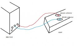
The B&K 9110 is a SINGLE supply. ONE of them cannot provide +/-28 volts. When you say '+/- 28 volt', I visualize THREE WIRES coming from a DUAL supply. A single 9110 cannot give the V6HP what it needs. The third binding post is surely an Earth ground, and the supply voltage FLOATS with respect to it -- it cannot provide the return path for the output current that you need.
Sorry about the awful sketch, but if that's how its wired, it won't work.
The point 'PRR' made is solid, too.
Regards,
--Rick
Attachments
Thanks for your reply. It seems like I won't be able to do this with just a SINGLE one, so would you be able to tell me how to wire it so that it will work (whether its with 2 power supplies or whatever).
Thanks Leica Chi
Thanks Leica Chi
If we could, I'd like to revisit the original issue. If you could find a small plate of soft iron, around 1 or 1.5 mm thick (0.8 mm would work somewhat, too), to fold up into a 5-sided box to contain the Jensen input transformers. Then position it so that the open side faces away from the V6-HP's power transformer. It might attenuate the hum enough that you could go back to using the original power supply.
If it works, that would be the tidiest solution.
If you're really sure that you want to try auxiliary power -- sure enough to spend some more money -- the best solution is called a 'dual tracking power supply'. It has a black binding post to connect to the ground (common connection between the main filter caps; or transformer center tap) of the amp. Then red and blue binding posts to connect to the BD139 and BD140 collectors, respectively. The magic is that both voltages ramp up or down at approximately the same time. This avoids the damage that can be caused by one rail coming up late.
You COULD buy another B&K 9110 -- another weak sketch below, to show how to connect that. But you'll want to be pretty careful to turn them both on and off together -- not to the millisecond, but within probably a half second or so. Setting the current limit a little lower, maybe 100 to 250 mA, will help since it'll have to charge the filter caps and so rise more gracefully.
Good luck and regards,
Rick
Last edited:
Hi Rick,
I will find dual output D.C. Power supply to try it , of course, I will follow
Your suggest . Thanks !
Leica chi
I will find dual output D.C. Power supply to try it , of course, I will follow
Your suggest . Thanks !
Leica chi
- Status
- Not open for further replies.
- Home
- Amplifiers
- Power Supplies
- AKG headphone amp V6HP mod power problem