
While on the topic of bulbs, I would imagine these are fed directly off a low voltage winding of the mains transformer and it is plausible that mains voltage variations could cause a noticeable increase or decrease in heat output from a bulb. A 10% mains variation for example would make a noticeable difference I suspect.
Wiring of the bulb may also have intermittent contact so in daylight it may be missed whether the meter backlight is on or not.
But the bulb is in rather closed space and near the speaker selector switch so it seems like a probable suspect...
Edit:
The 3 meter bulbs are in parallel so if one of them is blown then the remaining ones will get excessive voltage and generate more heat...

But the bulb is in rather closed space and near the speaker selector switch so it seems like a probable suspect...
Edit:
The 3 meter bulbs are in parallel so if one of them is blown then the remaining ones will get excessive voltage and generate more heat...
Last edited:
Well, the heat issue is said to be recent (reading the original post). Therefore, I doubt the lamps are the cause.
Right now it would seem to be a case of figuring out what changed, where is the additional heat coming from. So, with the information provided, it isn't the power switch, not the speaker switch.
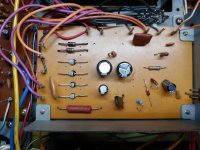
That leaves one thing to look for. A source of heat in that area. Look for discoloured resistors (most likely).
One thing I should stress, power switches and relay contacts must be dry. No dielectric grease ever! No oil, no contact protectant. Anything that switches power will arc. That will burn any substance between the contacts for sure. To extend contact life, reduce or eliminate the arc. That's all you can do beyond avoiding unnecessary loads through the switch or relay.
Right now it would seem to be a case of figuring out what changed, where is the additional heat coming from. So, with the information provided, it isn't the power switch, not the speaker switch.
That leaves one thing to look for. A source of heat in that area. Look for discoloured resistors (most likely).
One thing I should stress, power switches and relay contacts must be dry. No dielectric grease ever! No oil, no contact protectant. Anything that switches power will arc. That will burn any substance between the contacts for sure. To extend contact life, reduce or eliminate the arc. That's all you can do beyond avoiding unnecessary loads through the switch or relay.
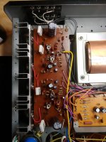
Apologies for not addressing your concerns earlier, but I did check for them, @anatech ! That's what had drawn me towards the power switch originally, knowing its history I had to confirm it's still in good working state. No loose wires were found in the area; only a wire-wrapped terminal on the common ground anchor had a bit of residue on it - looks to be resin - it still makes a good connection.

After initially servicing this amp, it ran "perfectly fine" for several years. Something could be affecting it externally, like the electrical grid in our home, though I have my doubts because it likely had shown faults sooner. Being in Germany, however, a drift of 23 V on our 230 V supply must be expected.
To summarize this heating issue, it appeared suddenly and without announcement, on different-fused outlets, and it doesn't seem to have an effect on the amp's sound or performance. Again, if memory serves, one time the unit was overheating to the point where I could feel it through the heat vents above the output board, which it never had done before. Hereafter it got temporarily decommissioned, and I would sporadically check if it was still heating up until I wrote this inquiry.
Being an amateur in electronics (at best, I think), I cannot rule out having overlooked something that would seem basic to others. All resistors on the power & output boards measure as expected according to the SM, and no components look burnt or broken (to me); I also cleaned the boards with 91% alcohol again.
Before the recent disassembly, DC Offset was matched to 64 VDC, and BIAS set to 40 mA from the fuse holders, holding rather steadily after hours of idling.

Given the suddenness of the defect and it exhibiting intermittently, one would assume some component(s) had become faulty. But lacking experience I struggle to find it or conclude what the source of the issue could actually be... I suspect the faceplate getting warm to be only a symptom of something worse at fault. Should I look somewhere else specifically or do I put the unit back together and start taking measurements?
On the topic of power switches:
Back when I started overhauling the amp, I also came across the triac mod which then hadn't been out for too long. Now it would seem my type of power switch should work well with this modification. Could anyone with experience in the matter tell me whether I should pursue this next?
After initially servicing this amp, it ran "perfectly fine" for several years. Something could be affecting it externally, like the electrical grid in our home, though I have my doubts because it likely had shown faults sooner. Being in Germany, however, a drift of 23 V on our 230 V supply must be expected.
To summarize this heating issue, it appeared suddenly and without announcement, on different-fused outlets, and it doesn't seem to have an effect on the amp's sound or performance. Again, if memory serves, one time the unit was overheating to the point where I could feel it through the heat vents above the output board, which it never had done before. Hereafter it got temporarily decommissioned, and I would sporadically check if it was still heating up until I wrote this inquiry.
Being an amateur in electronics (at best, I think), I cannot rule out having overlooked something that would seem basic to others. All resistors on the power & output boards measure as expected according to the SM, and no components look burnt or broken (to me); I also cleaned the boards with 91% alcohol again.
Before the recent disassembly, DC Offset was matched to 64 VDC, and BIAS set to 40 mA from the fuse holders, holding rather steadily after hours of idling.
Given the suddenness of the defect and it exhibiting intermittently, one would assume some component(s) had become faulty. But lacking experience I struggle to find it or conclude what the source of the issue could actually be... I suspect the faceplate getting warm to be only a symptom of something worse at fault. Should I look somewhere else specifically or do I put the unit back together and start taking measurements?
On the topic of power switches:
Back when I started overhauling the amp, I also came across the triac mod which then hadn't been out for too long. Now it would seem my type of power switch should work well with this modification. Could anyone with experience in the matter tell me whether I should pursue this next?
Attachments
Last edited:
Hi taperrrick87,
The manual is not very precise. Your DC offset (at the negative terminal of C9) should be a volt or two over 1/2 B+. B+ is approximately 62 VDC, so you'd probably want to set it to +33 VDC. The reason it is higher is because the power supply sags under load. The exact way to set it is under load into an 8R load and adjust for equal clipping. +33 VDC is close enough, 1/2 B+ will have you clipping on the negative waveform sooner.
Please confirm this is correct first. You stated it was set to 64 VDC. Then reconfirm the current draw for each channel is 40 mA approx. This will vary with heat sink temperature and the ambient temperature inside the case.
Power switch modifications. Wait, do not do anything until this is running properly.
Triac switching always involves the damager of not being 100% matched + and - phases. This creates an effective DC current and can burn out a transformer very quickly. Carver amplifiers using triac control have a circuit that carefully makes sure the phases are equal. Triac sensitivity is not the same each way. If you're that worried, later use a power relay with a 230 V coil. That will work fine. What also works wonders for saving switches are MOVs across the primary. They absorb the reverse kick from the transformer when you switch off, this is what arcs and kills switches. As a side benefit, it helps protect against voltage surges. Make sure it is right across the transformer, behind the power switch and fuse. It may short if you get a big surge (a really good thing!).
I would still recommend starting from the most simple thing - disconnect the transformer secondary feeding the bulbs.Given the suddenness of the defect and it exhibiting intermittently, one would assume some component(s) had become faulty. But lacking experience I struggle to find it or conclude what the source of the issue could actually be...
If the problem disappears, it is bulbs related, otherwise not.
TLDR: Everything is adjusted and stable again. As of right now, after idling for several hours, the faceplate does not seem to warm up.
Observations:

I’m seriously looking at purchasing an infrared thermometer to take notes should it warm up again. 🙂
While I’m at it, should I order one of these 275VDC Varistors as well? https://www.reichelt.de/de/en/varistors-vdr--c8406.html?ACTION=2&GROUPID=8406&SEARCH=*&START=0&OFFSET=16&CCOUNTRY=445&LANGUAGE=en&nbc=1&r=1&SID=943a48b9de6d289640346dc098b02fda74a9f4f02a69a88178109
Should I be looking at replacing other parts, f.e. the adjustment pots, for good measure?
@madis64 That would be the mint-colored lead, left of the filter cap. However, with the faceplate currently not heating up, I'd rather wait with untangling this mess:

The barren illumination on this model is apparently a hot topic of debate amongst owners; anyhow the bulb is mounted correctly. I had recently pulled it higher as to distance it further from the speaker selector. In the picture you can see the translucent plastic at the bottom of the meter where light is supposed to enter. Examples of strongly lit scales are of either modded units or perhaps the pictures were edited. My bulbs are aftermarket replacements, however prior to the recent issues they had not gotten warm.

Last night I reassembled the unit and gave it a 15 min test run without making any adjustments. I think the faceplate didn’t warm up, and the amp still operated as expected.
This morning I had let it run a bit and began setting DC offset to 33 V for each channel when I thought I had noticed the area on the faceplate was getting warm again. I then proceeded to measure BIAS and was getting no more than 28 mA on either channel after idling for more than 15 minutes. (Prior to the recent most disassembly, BIAS was adjusted to 40 mA per Channel) So I surmise increasing DC offset to also affect current draw. Why they would be listed in opposite order in the service manual is beyond me. Anyway the adjustments are holding steadily.
Observations:
Upon switching on the amp the left channel’s draw spikes close to 30 mA, falls down to around 12 mA, and then slowly rises; the other not as drastically. Is this indicative of a defective component?
Something I had noticed years ago when overhauling it, though not thereafter when the amp was installed on the shelf, is that the faceplate carried a slight “buzz”/current relative to which way the plug was inserted into the outlet. Only now, with the unit set up in the workshop, did I notice it again, and it is in this context that I thought to have noticed the faceplate warming up the last time. As seen in the service manual, my unit seems to be the region-unspecific version. Could this be relevant to the issue at hand?
I’m seriously looking at purchasing an infrared thermometer to take notes should it warm up again. 🙂
While I’m at it, should I order one of these 275VDC Varistors as well? https://www.reichelt.de/de/en/varistors-vdr--c8406.html?ACTION=2&GROUPID=8406&SEARCH=*&START=0&OFFSET=16&CCOUNTRY=445&LANGUAGE=en&nbc=1&r=1&SID=943a48b9de6d289640346dc098b02fda74a9f4f02a69a88178109
Should I be looking at replacing other parts, f.e. the adjustment pots, for good measure?
@madis64 That would be the mint-colored lead, left of the filter cap. However, with the faceplate currently not heating up, I'd rather wait with untangling this mess:
The barren illumination on this model is apparently a hot topic of debate amongst owners; anyhow the bulb is mounted correctly. I had recently pulled it higher as to distance it further from the speaker selector. In the picture you can see the translucent plastic at the bottom of the meter where light is supposed to enter. Examples of strongly lit scales are of either modded units or perhaps the pictures were edited. My bulbs are aftermarket replacements, however prior to the recent issues they had not gotten warm.
Hi taperrrick87,
Inrush current limiting on such a small amplifier isn't a big concern. What kills power switches is more arcing at turn-off.
Service manuals commonly have typos or are completely wrong. The bane of a warranty centre, believe me!
Try replacing the light bulbs with warm white LEDs. 8 - 16 mA current should do it (limit with a resistor). I do this and you can't tell it isn't a real lamp, that would totally solve any heat issue for all time.
The leakage current you feel is not uncommon. As for bias current variation, yes. Something could be out. It could be from new due to high or low beta in one of more devices. Hard to say without having it on my bench. But since it returns to normal levels I wouldn't worry to much. Run it up, get it waram and see if both bias currents are close once you warm it up. You must measure with no signal.
No. It is simply the effect of the thermal compensation (those 3 diodes in a single package) taking time reach the same temperature as the output transistors. All normal.Upon switching on the amp the left channel’s draw spikes close to 30 mA, falls down to around 12 mA, and then slowly rises; the other not as drastically. Is this indicative of a defective component?
After installing the unit back into the hifi-shelf, I gave it a couple of test runs at close to ½ of full volume. With the top cover back on I thought I noticed on the first run the output board under the heat vents getting a bit warm, yet the faceplate was completely cold. However, this did not reproduce on the next runs blasting my favorite mixtapes.

Should the front area warm up again, I'll modify it with LEDs as instructed. 🙂 Stressing the unit brought the bias currents up to 63 mA (L) and 69 mA (R), and after cooling off and power-cycling the unit idles at 40 mA each again. So that should be within expectation, right?
Curiously, in this room the leakage current/buzz was much less noticeable. When I connected my turntable, it even went away entirely, just as I remembered it.
While I'm in the middle of giving this amp a check-up, I would greatly appreciate your insight on a couple minor things about the inputs that have me clueless:
There’s a bit of crosstalk onto the tape inputs, faintly there would be the radio playing when the cassette was finished and the volume was turned loud enough. What could likely have failed at keeping them separate or is there an adjustment that I have to make?
Unless the tape selector is engaged, there’s a ground hum present on the inputs. It’s only really audible with the volume quite loud, but it still has me a bit concerned. If it’s any indication there’s a distinct pop when switching away from/to the radio that I attributed to ground issues, because it’s gone when I neglected to attach the antenna tonight.
Hi taperrrick87,
Your bias looks okay. Not unexpected and varies between brands and models. No worries.
The leakage could be time of day or anything related. It can be measured but is probably within spec.
Crosstalk is completely expected, no worries. If you measured it, it would probably fall in spec. Measured with a loaded input of course, an open input will be much louder. If that source is off, it would be louder also.
Again, if you measured it as signal to noise, you are probably better than spec.
Alright, I think the amp's gonna stay like it is for now. Until these issues worsen I'm going to continue to ignore them, as they're only noticeable when focusing on/provoking them. Should anything come up in relation to overheating I'll update this post.
Thanks to everyone for their time and walking me through the process! Hopefully I've learned a couple things and will be doing much better on my next projects.
Best regards
taperrrick87
Thanks to everyone for their time and walking me through the process! Hopefully I've learned a couple things and will be doing much better on my next projects.
Best regards
taperrrick87
- Home
- Amplifiers
- Solid State
- AKAI AA-1020 heat issue on faceplate