Hi all. I like to think I’m not totally incompetent but I am totally new to vintage amps.
I purchased an akai 1020 in really great condition. All that was needed were new led bulbs which I did. When it arrived only the right channel was working but I quickly figured out a blown fuse was the culprit.
Everything seems in order but to be safe I bought some contact cleaner and she’s really nice and clean. No pops, crackles, etc. I’m not an electrical engineer though and have struggled with a good chunk of the terminology. I think I’ve read every single available post on this model though. I’ve only visually inspected the caps but they’re all in good visual condition. I know an amp of this age should be re-capped, it’s definitely something I intend to do.
My struggles relate to balance and current adjustments though. The service manual says to balance each side to 40 mA but no matter what I try, both channels are only at 24. If I move the potentiometer to the max each way, it will go down to 23 and up to 25.
And when I try to set the DC balance, the advice is to to set each point to half of supply voltage , but I’ve no idea what that figure is, at the risk of sounding very dumb, is that 230v or just the voltage the rail is pulling from the mains?
I did say I wasn’t an electrical engineer so again, I’m sorry if I sound stupid.
I do want to get it looked at properly by an expert but given lockdown, it’s not possible.
Apart from not knowing what the values should be or how to get there, the amp sounds genuinely lovely. I’ve got it paired with a set of wharfedale Denton 80th anniversary speakers. They are rated from 20-100 watts so the amp does just scrape in there in terms of minimum power recommended but it does a great job.
Thanks in advance to anyone who can help.
Ryan
The midpoint voltage is one half the supply voltage which in the manual is shown as approx 62 volts. So you set the midpoint to around 31 volts. You measure it on the positive side of the big speaker coupling capacitor.
Bias current is set (easiest way) by measuring the voltage across the lower 0.47 ohm in each channels output stage. That is R18 in the manual.
40 milliamps would equate to a voltage of 18 millivolts (so a small voltage). Its just ohms law to calculate the voltage required. V=I*R which is 0.04*0.47.
Bias current is set (easiest way) by measuring the voltage across the lower 0.47 ohm in each channels output stage. That is R18 in the manual.
40 milliamps would equate to a voltage of 18 millivolts (so a small voltage). Its just ohms law to calculate the voltage required. V=I*R which is 0.04*0.47.
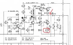
Like this (much better):
How to attach images to your posts.
Make sure you adjust the correct preset for the idle current. It is VR2.
VR1 sets the midpoint voltage which is measured where arrowed.
How to attach images to your posts.
Make sure you adjust the correct preset for the idle current. It is VR2.
VR1 sets the midpoint voltage which is measured where arrowed.
Attachments
This is called a single supply amplifier. Use your digital voltmeter to check that voltage on C1 (6800uF at 63V rating).
There are two adjustment controls for each amplifier channel. One is for bias current (amount of DC current in the output transistors).
One is for offset (DC voltage at the output before the coupling capacitor should be half the voltage on C1).
The procedure is on page 11 of the service manual.
Akai AA-1020 AM/FM Stereo Receiver Manual | HiFi Engine
Oh wow, I really wasn’t expecting such a brilliant and prompt reply. Thank you both . My dc was off, it was sitting at 27v but even turning the semi fixed resistors (vr1) to max, I only get 30.5 in the right channel and 30.4 in the left. Although, the fact I have to max out the adjustment probably suggests a freshen up is needed, new caps or is that too basic?
I have the service manual and that was telling me to measure at the fuse holder on the underside!!!
I’m getting a steady 26 mA on both channels but it doesn’t change no matter how much I adjust.
I have the service manual and that was telling me to measure at the fuse holder on the underside!!!
I’m getting a steady 26 mA on both channels but it doesn’t change no matter how much I adjust.
Last edited:
You should verify that the main voltage is actually 62VDC.
If it is only (say) 50VDC, then the adjustment should be for 25VDC at the output instead.
This adjustment is not that critical, though it should be reasonably close.
Is your current reading 0.25A or 0.25mA? The idle current adjustment is very important.
You did remove the fuse, when measuring the current at the fuse holder?
Last edited:
But yes. I’m definitely measure mA (DC) and it’s slowly fluctuating between 0.24 and 0.26. The amp has been on for a few hours too.
But yes. I’m definitely measure mA (DC) and it’s slowly fluctuating between 0.24 and 0.26.
Are you sure that is 0.26mA? The correct bias current is 40mA. Something is not right.
If you are very careful, maybe it would be better to check the voltage drop across the 0.47 ohm emitter resistor as mentioned before.
Since the resistor is 0.47 ohms, the voltage drop across it for 40mA bias current is (0.47R x 0.040A) = 0.019VDC (or 19mV).
You will find R18 and R18b (one per channel) clearly marked on the diagram of the pc board layout (on page 16 of the linked manual).
But you have to put all the fuses back in for this measurement. Use VR2 when measuring R18, and use VR2b when measuring R18b.
Last edited:
Just to update. I’m reading 0.17 mV on R18. Which if I’m reading correctly, is the first of the 4 white, square transistors that are labelled with “0.47”
Thanks again Rayma. I know this may be frustrating to you that I’m not better at this.
Thanks again Rayma. I know this may be frustrating to you that I’m not better at this.
Last edited:
The R18 is a resistor. It's a 0.47 ohm, 5 watts, wirewound power resistor.
The voltage reading across R18 is way too low. It should be 0.019VDC (or 19mV).
Could you be misreading the meter, is it set to DC volts?
How about the other channel, across R18b?
Make sure the red meter probe is plugged into the right meter socket.
The red lead goes to a different socket on the meter when measuring amps (current), than when measuring volts.
You have to manually move the red plug between the two different meter sockets. The black probe stays put.
If the other channel's reading is similar, test your meter (on volts) by measuring a flashlight battery (AA, C, or D cell).
That reading should be somewhere around 1.56VDC.
Turn off the amplifier's power switch (or unplug it), and after about 10 seconds touch the heat sink. Is it cold, warm, or hot?
Last edited:
Yes, sorry. I meant resistor and I googled the part (mpc71) to be sure we’re talking about the same thing. I have my meter set to dc mV and it has an auto range. (The V sign with a horizontal line next to it and three dotted line under that one). My red lead is plugged into the V socket and not the A one.
I think my adjusters are just not great. I’m able to now adjust r18 and r18b but when I get one right, I measure the other and it’s out of spec again. I assume there’s some sort of settling in time after a measurement? I also notice the voltage drops when I take the screwdriver out of the adjuster a little!!! I think I’m getting there though. Aiming for 19.0 mV as suggested.
I think my adjusters are just not great. I’m able to now adjust r18 and r18b but when I get one right, I measure the other and it’s out of spec again. I assume there’s some sort of settling in time after a measurement? I also notice the voltage drops when I take the screwdriver out of the adjuster a little!!! I think I’m getting there though. Aiming for 19.0 mV as suggested.
It's normal that the two channels interact when adjusting the bias current, due to the common power supply.
See if you can get the bias current in both channels to about the right 19mV, by going back and forth a few times.
The settings don't have to be exact, and the resistors are probably not real precise anyway since they're +/- 10%.
After these are about right, recheck the output DC offset, it might have changed.
Check it by measuring the C1 voltage, and then adjusting for half of that at the output.
Then recheck the two bias current settings to see if that changed them. Once everything is close, try it out.
Last edited:
This forum has been a god-send honestly. I’ve got them both floating between about 18.7 and 19.1. I’ve come to the conclusion my multimeter leads aren’t the greatest!!!
Checked the DC and it did go off slightly so bumped it back to 29V.
I’m so glad I asked and even more so that all of you replied. Given the DC was originally at 27 and idle was, well, god knows where.
It is odd that I could get a proper reading from the resistor rather than the fuse holder but so be it.
This has been the most helpful and clear thread I’ve seen on this topic so I hope it helps other too. Although, I doubt there’s few less capable than I.
Thank you again, I’ll sit back and enjoy for a while until I start getting obsessive about a re-cap job now.......
Next week on “diy audio” - help! there’s a fizzing noise coming from my receiver.......
Thanks again Rayma. Take care.
Thanks again Rayma. Take care.
Good to hear you are getting there 🙂
Both the adjustments will tend to drift with temperature. The midpoint volts is not critical, it simply ensures the amp clips symmetrically at maximum output and so a volt or two either way will have no impact at all.
Bias current is the critical one. You really need to tweak this when the amp is at normal operating temperature and accept that it will vary considerably between checking when cold and checking when hot.
It is most important not to set it to high as that increases the heat developed in the output transistors and can also make the amp more prone to thermal runaway. This where the bias increases, the amp gets a bit hotter, the current increases some more and so on...
I couldn’t quite believe how much it drifted at some points! I could never get it bang on 19 but I’d get it close, check it ten mins later and after adjusting the other side and the first side had gone down to about 15!
I still think it needs a freshen up and taken to a professional but I’m a lot happier that it’s now where it should be. I’m just very wary of constantly going back and back forth to check it and open the thing up all the time. As well built as it is , she’s not young and every time in open her up and disconnect all the gear, there’s a chance something will break. I do however put my hand over the vent every now and again and I’ve never felt warmth. Even when it has been open and on the heat sink has never been warm to the touch. I suppose I just don’t need to push it that hard in my listening room.
It really does sound so nice though, I was worried 20w wouldn’t be enough but it’s more than. I get what everyone says about the vintage gear! I had a good solid budget one previously, an onkyo given to me by a friend to get started but This Akai blows it out the water
- Home
- Amplifiers
- Solid State
- Akai 1020 service help