Hi all,
I have made an ADC based on the AK5394a which presumably performs very well but behaves oddly when I connect a sine wave generator to the ADC input circuitry.
By "oddly" I mean that the signal displayed by the signal analysis software I use (wave spectra) in no way looks like what it is supposed to look like ... It is becoming quite frustrating so I hope that somebody here may help say what may be causing this phenomenon - I would much appreciate this 😉
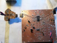
I have attached a copy of the schematics involved (pictures 1 and 2). The circuitry is split in two so that one PCB contains the input circuitry and then there is a main PCB which basically contains the ADC (picture 3).
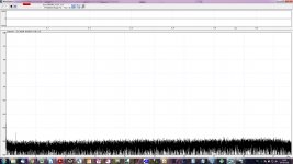
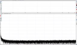
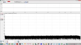
When the input is shorted the ADC output looks like picture 4. Very low noise and basically no issues.
When the input is "open" i.e. nothing is connected to the input it still looks flat, however, at a somewhat higher basic noise level (around - 120 dB). This is to be expected as the 220k input resistor now is not paralleled with the output impedance of a DUT.
... so far so good, no real issues (also keeping in mind that everything is placed out in the open, no shielding at all) ...
All circuitry parts BTW are battery supplied, floating, so that each part has its own battery supply (no ground loops).
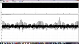
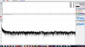
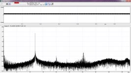
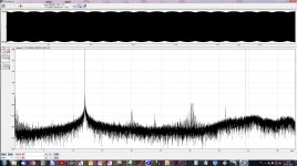
However, when I then connect the sine wave generator (Victor's sine wave generator 12 kHz version, - 133 dB THD, 600 ohm output impedance, single-ended output) the ADC output changes completely! This is shown in picture 5.
Basically, it looks nothing like what it is supposed to look like - and decoupling the input with up to 12 nF parallel with the 220k input-to-ground resistor (~280 kHz - 3 dB low pass point when connected to a DUT) does not really change things ...
So I wonder what could be amiss here? As it is I have used the input circuitry PCB (picture 1) in another context (LTC2380-24 ADC) where it performs fine with a distortion level around -120 dB (2H).
If you have some suggestions as to what may be the culprit causing this behavior, I would appreciate your input ...
Cheers & thanks,
Jesper
I have made an ADC based on the AK5394a which presumably performs very well but behaves oddly when I connect a sine wave generator to the ADC input circuitry.
By "oddly" I mean that the signal displayed by the signal analysis software I use (wave spectra) in no way looks like what it is supposed to look like ... It is becoming quite frustrating so I hope that somebody here may help say what may be causing this phenomenon - I would much appreciate this 😉
I have attached a copy of the schematics involved (pictures 1 and 2). The circuitry is split in two so that one PCB contains the input circuitry and then there is a main PCB which basically contains the ADC (picture 3).
When the input is shorted the ADC output looks like picture 4. Very low noise and basically no issues.
When the input is "open" i.e. nothing is connected to the input it still looks flat, however, at a somewhat higher basic noise level (around - 120 dB). This is to be expected as the 220k input resistor now is not paralleled with the output impedance of a DUT.
... so far so good, no real issues (also keeping in mind that everything is placed out in the open, no shielding at all) ...
All circuitry parts BTW are battery supplied, floating, so that each part has its own battery supply (no ground loops).
However, when I then connect the sine wave generator (Victor's sine wave generator 12 kHz version, - 133 dB THD, 600 ohm output impedance, single-ended output) the ADC output changes completely! This is shown in picture 5.
Basically, it looks nothing like what it is supposed to look like - and decoupling the input with up to 12 nF parallel with the 220k input-to-ground resistor (~280 kHz - 3 dB low pass point when connected to a DUT) does not really change things ...
So I wonder what could be amiss here? As it is I have used the input circuitry PCB (picture 1) in another context (LTC2380-24 ADC) where it performs fine with a distortion level around -120 dB (2H).
If you have some suggestions as to what may be the culprit causing this behavior, I would appreciate your input ...
Cheers & thanks,
Jesper
Attachments
Last edited:
Is the input clipping?
What have you set the OCM voltage for the OPA1632 to?
Is the driver circuit stable with the load applied?
Can you provide a time domain (oscilloscope) measurement of the input signals to the ADC?
Some comments.
I would remove C3, C9, C27 and C32. They are not shown in the AK5394A datasheet and I have seen no need for them.
The series resistors R3, R6, R16 and R18 will probably increase the distortion dramatically. But probably not enough to explain your strange spectrum. I suggest that you make the feedback as shown in figure 9 in the datasheet.
I am surprised that you use capacitors directly in parallel with the feedback resistors of the AD797's. Normally it doesn't like that, see the datasheet.
Hi Jens,
Thanks for your fine feedback ;-) ... I will check out your inputs, make oscilloscope measurements, and get back tomorrow late afternoon or evening.
Cheers - Jesper
Thanks for your fine feedback ;-) ... I will check out your inputs, make oscilloscope measurements, and get back tomorrow late afternoon or evening.
Cheers - Jesper
The waveform is DC offset - and appears to have 100Hz modulation (both from the wave plot and the spectrum).
Is this a virtual ground to mains earth issue (lack of DC-blocking caps?)
Is this a virtual ground to mains earth issue (lack of DC-blocking caps?)
Hi Jens & Mark,
Thanks again for your feedbacks 😉 ...
As it is I have been looking into this all day and I cannot really get a grip on what is happening here ... ??
However, I'll try to describe what is going on and hope you may have suggestions as to what can be done (while also relating to the suggestions & comments you have made):
@ JensH:
I have not seen any signs of the driver circuitry oscillating or the like. The 12 kHz sine is there all the time and looking at a spectrum (oscilloscope) of the 12 kHz sine it appears to be clean.
https://www.diyaudio.com/forums/digital-line-level/273474-dac-dac-221.html#post5826117
I realize that this in an input (his comment is about a DSD output) but I reckon something similar may apply to an input .... In any case its - 3 dB point is around 280 kHz so my guess is that it cannot cause what is happening here (but please feel welcome to comment additionally ...)
I suppose that you are talking about an increased settling time between samples due to the output of the OPA1632 not coupling directly with the ADC inputs? If so, or other reason?, I will remove them (haven't tried it yet, though).
But if you may suggest another input circuitry that is good enough for the AK5397 I would appreciate seeing it (to my memory you and 1audio talked about this in relation to your own AK5397 design).
@Mark Tillotson: Thanks again for your feedback. I reckon there may be something to what you are suggesting because the basic noise level of the FFT may fluctuate up and down as if it were floating on top of a maybe 1 - 2 Hz sine "noise modulator". This goes on from the basic ~-160 dB level and then up to appr. an -80 dB level ... (pictures 2 and 3) ... 😕
However, the only mains connected device is the laptop. Victor's oscillator, the input circuitry, and the ADC supply voltages are all battery supplied (and each part of the circuitry from its own battery) so as to avoid any ground loops or the like. Additionally there's a digital isolator inserted between the ADC digital outputs (SCLK, LRCK, DATA) and the USBPAL digital inputs.
That said I have tried to insert a capacitor between Victor's oscillator and the AD797/OPA1632 input circuitry - but it didn't really change things.
I have also tried to insert a capacitor between each of the OPA1632's outputs and the ADC inputs and here something happened - the basic noise level attenuated somewhat and allowed for the sine generator's 12 kHz signal to be clearly seen although only briefly. It did disappear again, however, after maybe 5 seconds (and I couldn't repeat it and didn't have time to make a screen dump). And I also noticed that measuring the DC level between the ADC inputs while the capacitors were in place showed an appr. 2 volt difference (the OPA1632's OCM output is now blocked by the capacitors) ...
......
Probably mostly @JensH: I have also measured the voltages on the VcomR and VcomL as well as the VREF voltages and they are slightly different than what is indicated in the datasheet PIN/FUNCTION descriptions. Could it be that the ADC is somehow damaged? The differences are not huge - maybe 50 - 100 mV but they are there ...
I have also checked all ADC pin connections etc. and everything appears to be as it should be.
I have mounted some additional 100 nF capacitors on VA and VD - for additional PSU filtering - and wouldn't guess that this could be anything but positive ... but ... ??
I also made the Vref capacitors larger than 1000uF (which is the suggested maximum in the data sheet) - 2200 uF instead as I would like the ADC's low distortion to be there also at low frequencies. Do you think there may be any risk it could have damaged the ADC? To this end I also increased the reset release to appr. 30 seconds so that the ADC would have time to settle before the calibration takes place.
@both of you: I have also noticed that it is not unusual that when I turn up the output volume from Victor's oscillator it often results in the 12 kHz not really being clearer but the overall noise level increasing. Sort of like picture 3 in #1 but the noise level climbs upwards ... 😕
Summing up: I admittedly do not know what is going on here so any suggestions on your parts would be most appreciated. Somehow my feel is that the ADC itself may/might work - the 12 kHz sine appears from time to time - and also the input circuitry. But this odd performance with levels shifting does remind me of the oddities of oscillations in analog circuitry ... but they seem not to be there ... I'm genuinely puzzled here ...
Well, this has become a long post ... if you made it this far then thanks for reading 😉 and hopefully knowing what may be going on ...
Have a good evening ..
Jesper
Thanks again for your feedbacks 😉 ...
As it is I have been looking into this all day and I cannot really get a grip on what is happening here ... ??
However, I'll try to describe what is going on and hope you may have suggestions as to what can be done (while also relating to the suggestions & comments you have made):
@ JensH:
... I don't think so. Even when I lower Victor's oscillator to its lowest level (~0.4 Vpp) the same phenomena happens. Also, the oscilloscope shows a pure sine on the input.Is the input clipping?
... The OCM voltage is set to VA/2 +/- 1->2 mV. If you remember the ADC input circuitry from post #1 the OCM voltage is taken from VA (here called ADC_COM_1) and then divided in a trimmer with two capacitors shorting noise. Thus OCM voltage typically is very close to VA/2.What have you set the OCM voltage for the OPA1632 to?
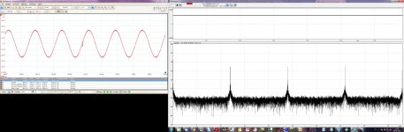
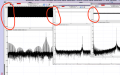
... Yes, it appears to be so. I have attached a picture (picture 1) showing the input signal (oscilloscope) next to the FFT (wave spectra). It is a pretty clear 12 kHz (the spikes on the 12 kHz appears to be due to a noisy oscilloscope input. It is not there on the other oscilloscope channel).Is the driver circuit stable with the load applied?
I have not seen any signs of the driver circuitry oscillating or the like. The 12 kHz sine is there all the time and looking at a spectrum (oscilloscope) of the 12 kHz sine it appears to be clean.
... Well, I have designed the capacitor filtering inspired by the LTC2380-24 input circuitry (datasheet p.31) and also this comment from JohnW (John Westlake I think it is) in this post:I would remove C3, C9, C27 and C32. They are not shown in the AK5394A datasheet and I have seen no need for them.
https://www.diyaudio.com/forums/digital-line-level/273474-dac-dac-221.html#post5826117
I realize that this in an input (his comment is about a DSD output) but I reckon something similar may apply to an input .... In any case its - 3 dB point is around 280 kHz so my guess is that it cannot cause what is happening here (but please feel welcome to comment additionally ...)
The series resistors R3, R6, R16 and R18 will probably increase the distortion dramatically. But probably not enough to explain your strange spectrum.
I suppose that you are talking about an increased settling time between samples due to the output of the OPA1632 not coupling directly with the ADC inputs? If so, or other reason?, I will remove them (haven't tried it yet, though).
... Hmmm .. The problem with fig. 9 is that it doesn't perform very well THD-wise, and my reason for choosing the AK5394 mainly was to get an ADC that will allow me to look into the -120 dB THD area. Also, as I mentioned in post #1, I have achieved -120 dB 2H with exactly this input circuitry using an LTC2380-24 - and here not knowing if it was the LTC2380-24 or the input circuitry that was the limiting part.I suggest that you make the feedback as shown in figure 9 in the datasheet.
But if you may suggest another input circuitry that is good enough for the AK5397 I would appreciate seeing it (to my memory you and 1audio talked about this in relation to your own AK5397 design).
.. I was aiming to obtain a flat response in a voltage follower configuration and if you look at the text preceding fig. 37 and also fig. 37 in the AD797 datasheet it is actually suggested that a 33 pF capacitor is paralleled with the 100 ohm feedback resistor. Based on previous experience I think it is working well ...I am surprised that you use capacitors directly in parallel with the feedback resistors of the AD797's. Normally it doesn't like that, see the datasheet.
@Mark Tillotson: Thanks again for your feedback. I reckon there may be something to what you are suggesting because the basic noise level of the FFT may fluctuate up and down as if it were floating on top of a maybe 1 - 2 Hz sine "noise modulator". This goes on from the basic ~-160 dB level and then up to appr. an -80 dB level ... (pictures 2 and 3) ... 😕
However, the only mains connected device is the laptop. Victor's oscillator, the input circuitry, and the ADC supply voltages are all battery supplied (and each part of the circuitry from its own battery) so as to avoid any ground loops or the like. Additionally there's a digital isolator inserted between the ADC digital outputs (SCLK, LRCK, DATA) and the USBPAL digital inputs.
That said I have tried to insert a capacitor between Victor's oscillator and the AD797/OPA1632 input circuitry - but it didn't really change things.
I have also tried to insert a capacitor between each of the OPA1632's outputs and the ADC inputs and here something happened - the basic noise level attenuated somewhat and allowed for the sine generator's 12 kHz signal to be clearly seen although only briefly. It did disappear again, however, after maybe 5 seconds (and I couldn't repeat it and didn't have time to make a screen dump). And I also noticed that measuring the DC level between the ADC inputs while the capacitors were in place showed an appr. 2 volt difference (the OPA1632's OCM output is now blocked by the capacitors) ...
......
Probably mostly @JensH: I have also measured the voltages on the VcomR and VcomL as well as the VREF voltages and they are slightly different than what is indicated in the datasheet PIN/FUNCTION descriptions. Could it be that the ADC is somehow damaged? The differences are not huge - maybe 50 - 100 mV but they are there ...
I have also checked all ADC pin connections etc. and everything appears to be as it should be.
I have mounted some additional 100 nF capacitors on VA and VD - for additional PSU filtering - and wouldn't guess that this could be anything but positive ... but ... ??
I also made the Vref capacitors larger than 1000uF (which is the suggested maximum in the data sheet) - 2200 uF instead as I would like the ADC's low distortion to be there also at low frequencies. Do you think there may be any risk it could have damaged the ADC? To this end I also increased the reset release to appr. 30 seconds so that the ADC would have time to settle before the calibration takes place.
@both of you: I have also noticed that it is not unusual that when I turn up the output volume from Victor's oscillator it often results in the 12 kHz not really being clearer but the overall noise level increasing. Sort of like picture 3 in #1 but the noise level climbs upwards ... 😕
Summing up: I admittedly do not know what is going on here so any suggestions on your parts would be most appreciated. Somehow my feel is that the ADC itself may/might work - the 12 kHz sine appears from time to time - and also the input circuitry. But this odd performance with levels shifting does remind me of the oddities of oscillations in analog circuitry ... but they seem not to be there ... I'm genuinely puzzled here ...
Well, this has become a long post ... if you made it this far then thanks for reading 😉 and hopefully knowing what may be going on ...
Have a good evening ..
Jesper
Attachments
The spectrum in your last post looks different from the spectrum shown in the first post. What changed?
Why do you have peaks at 12, 24, 36 and 48 kHz? It should only be at 12 kHz.
Is there something wrong with the digital interface?
I can see that you set the AK5394A to I2S, but does your digital input also use the I2S format? If not you may loose the sign bit and thereby distort the spectrum. I am only guessing here, but different interface standards can lead to strange results.
Have you checked the interface type and the timing of the I2S signals?
Regarding this: "The series resistors R3, R6, R16 and R18 will probably increase the distortion dramatically. But probably not enough to explain your strange spectrum.
I suppose that you are talking about an increased settling time between samples due to the output of the OPA1632 not coupling directly with the ADC inputs? If so, or other reason?, I will remove them (haven't tried it yet, though)."
You should not remove (short) the resistors unless you change the feedback as shown in figure 9 in the datasheet. The OPA1632 will probably not like the capacitive load directly on the outputs.
I once made a test where I inserted resistors in series with the ADC inputs. The 2n2 capacitor was still directly across the ADC input terminals.
I went from a THD of around -132 dB to a THD of -105 dB, so it didn't seem like a good idea.
Hi Jens - & thanks once more for your feedback. I have been looking into the ADC once more this morning and your questions/comments are quite relevant although the reason why this happens still remains illusive to me. But to address your comments:
Also, the digital interface (USBPAL) has dedicated I2S inputs - which normally work fine with my other ADC (AK5572). And I have carefully checked that the pins are located correctly relative to the USBPAL input pins. So, unfortunately, this doesn't appear to be the culprit.
I have not checked the timing of the I2S signals though - I assumed they would be timed from the ADC when set to master & I2S. But maybe you have experienced that they may be out of timing on your ADCs? Trace lengths are very close to being identical.
Anyway again this morning there was a "brief opening" where the spectrum displayed the 12 kHz for a couple of minutes and then it disappeared again. Looked like the attached picture .. unfortunately not remarkable ...
I think I'll have to consider how to progress ... One question though in this context: When you suggest the input coupling shown in fig. 9 in the datasheet - do you then have experience with this achieving the same performance as your RTX6001 device? Or do you think it would be close to this performance?
Cheers,
Jesper
... Basically nothing changed except that the actual spectrum shown in Wave Spectra often changes from power up to power up. Which is a bit unsettling.The spectrum in your last post looks different from the spectrum shown in the first post. What changed?
... I have been thinking the same. As you may have noticed in the ADC schematic I used 1k resistors to connect between the ADC itself and the digital isolator. I did this to reduce the currents drawn on the digital transmission since the GND connections on the AK5394 as I can see it also performs other functions and thus these currents might shift the GND level ever so slightly. However, I have changed all the transmission resistors back to normal values and it makes no difference in the spectrum.Why do you have peaks at 12, 24, 36 and 48 kHz? It should only be at 12 kHz.
Is there something wrong with the digital interface?
Also, the digital interface (USBPAL) has dedicated I2S inputs - which normally work fine with my other ADC (AK5572). And I have carefully checked that the pins are located correctly relative to the USBPAL input pins. So, unfortunately, this doesn't appear to be the culprit.
I have not checked the timing of the I2S signals though - I assumed they would be timed from the ADC when set to master & I2S. But maybe you have experienced that they may be out of timing on your ADCs? Trace lengths are very close to being identical.
Anyway again this morning there was a "brief opening" where the spectrum displayed the 12 kHz for a couple of minutes and then it disappeared again. Looked like the attached picture .. unfortunately not remarkable ...
I think I'll have to consider how to progress ... One question though in this context: When you suggest the input coupling shown in fig. 9 in the datasheet - do you then have experience with this achieving the same performance as your RTX6001 device? Or do you think it would be close to this performance?
Cheers,
Jesper
Attachments
A P.S.: Just came to think of if what you suggest in relation to fig. 9 in the datasheet is to modify each of the OPA1632 outputs to be like what is shown in fig 9. Just to be sure ;-)
Jesper
Jesper
Also, the digital interface (USBPAL) has dedicated I2S inputs - which normally work fine with my other ADC (AK5572). And I have carefully checked that the pins are located correctly relative to the USBPAL input pins. So, unfortunately, this doesn't appear to be the culprit.
I have not checked the timing of the I2S signals though - I assumed they would be timed from the ADC when set to master & I2S. But maybe you have experienced that they may be out of timing on your ADCs? Trace lengths are very close to being identical.
Have you checked that your digital interface (USBPAL) is set as I2S slave and the input format is I2S? And is your other ADC also working as I2S master?
I think I'll have to consider how to progress ... One question though in this context: When you suggest the input coupling shown in fig. 9 in the datasheet - do you then have experience with this achieving the same performance as your RTX6001 device? Or do you think it would be close to this performance?
A P.S.: Just came to think of if what you suggest in relation to fig. 9 in the datasheet is to modify each of the OPA1632 outputs to be like what is shown in fig 9. Just to be sure ;-)
Jesper
I used the feedback method of fig. 9 in the RTX6001. I did use different amplifiers though, with two LME49990's driving each input of the ADC.
But I think for now this should not be your main worry. Something basic, probably in the digital interface, seems to create bigger problems.
Could you zoom in on the time axis of the figure, so that we can see the waveform of what the ADC is seeing? This may help in pinpointing the problem.
The DC offset could perhaps be a consequence of timing problems or mixing I2S with a left-justified interface or something similar.
Hi all ... appreciate your feedbacks. Currently working to see if I can find/provide the kind of information you are addressing.
@JensH:
Unfortunately not. The maximum magnification of Wave Spectra is 20x in both X and Y axes and I cannot see that it is possible to zoom in any further. And the 12 kHz sine signal is just too frequent for a wave to be properly displayed ... :-(
One of you know of an alternative program that can help with this? Needs be functional as a demo at least at this point in time.
BTW on the oscilloscope it looks as if the input to the ADC is centered around VA/2 (=Vocm) and is a balanced signal. So something seems to be happening between the ADC and the PC ...
Cheers,
Jesper
@JensH:
Could you zoom in on the time axis of the figure, so that we can see the waveform of what the ADC is seeing?
Unfortunately not. The maximum magnification of Wave Spectra is 20x in both X and Y axes and I cannot see that it is possible to zoom in any further. And the 12 kHz sine signal is just too frequent for a wave to be properly displayed ... :-(
One of you know of an alternative program that can help with this? Needs be functional as a demo at least at this point in time.
BTW on the oscilloscope it looks as if the input to the ADC is centered around VA/2 (=Vocm) and is a balanced signal. So something seems to be happening between the ADC and the PC ...
Cheers,
Jesper
You can try audioTester. If your interface supports ASIO, you should use that to avoid resampling.
audioTester
audioTester
it has been a long time since I was working with the AK5394. I remember some quirkiness in the clocking that could get results like you have. Jen's would be more current on this. There are selections in the clock settings that you need to follow. The demo board docs have some info. It also has a great example of a bad crystal oscillator implementation. Switching to an external clock got the distortion down significantly. I have the demo board here somewhere if you need me to figure out the clock settings.
REW is free and has been really enhanced. ARTA has a demo mode as well. There are others. A quick search popped up several. The real high res options are limited.
This is the best tool I have found DiAna It can help you figure out what to focus on to improve the system. And the author is on DIYaudio. DiAna, a software Distortion Analyzer
Yes, e.g. REW and ARTA would also be useful here.
For now I think that a simple analysis with an oscilloscope function will be sufficient. Once the basic problem has been solved, a deeper analysis can be made.
For now I think that a simple analysis with an oscilloscope function will be sufficient. Once the basic problem has been solved, a deeper analysis can be made.
Hi Jens & 1audio,
& thank you both for your feedbacks 😉 ...
Incidentally I was just about to finalize this post with my measurements attached when my eyes caught sight of a notice in the USBPAL user manual - and given your comments about I2S format etc. I reckon this may actually be the culprit ... 😱
Thus, might I ask you to take a look at the top section of p. 18 in the attached user manual? Here it says that the default data input setting is left justified and one has to make a change in a USBPAL .inf file to set it up for I2S.
There is more specific configuration information in the user manual from p. 21. Specifically on I2S configuration of 96 & 192 kHz data inputs on p. 22 - top.
To this end I have searched the USBPAL driver installation folder for *.inf files and found one that appears to have a similar text as the text from p. 21 in the user manual. I have attached this .inf file as a text file.
However, with regards to what is to be changed this .inf text looks exactly the same as the information in the user manual - so I cannot see what needs be changed (and here it admittedly doesn't help that I am not a programmer). Any chance you may be able to help with this, Jens?
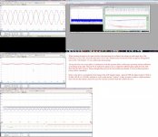
And then - just in case you are still interested I have attached a picture of the measurements I made this morning. From them I would say that it is quite obvious that the ADC doesn't output what it receives as an input (in audio tester) - and I reckon that skewing the bit input just one bit may actually cause this ... 🙁
@1audio: Besides REW and audio tester I also did take a quick look at DiAna and it looks quite interesting. Not least the ability to notch out the distortion wave-form. But it also looks as if it needs a loop (output-input device) to enable setup (from a quick glance that is)? Or did I miss something here?
... Would it indeed be great if this .inf file setting is what causes this! I really look forward to seeing what this ADC is capable of ...
Cheers again & appreciation,
Jesper
& thank you both for your feedbacks 😉 ...
Incidentally I was just about to finalize this post with my measurements attached when my eyes caught sight of a notice in the USBPAL user manual - and given your comments about I2S format etc. I reckon this may actually be the culprit ... 😱
Thus, might I ask you to take a look at the top section of p. 18 in the attached user manual? Here it says that the default data input setting is left justified and one has to make a change in a USBPAL .inf file to set it up for I2S.
There is more specific configuration information in the user manual from p. 21. Specifically on I2S configuration of 96 & 192 kHz data inputs on p. 22 - top.
To this end I have searched the USBPAL driver installation folder for *.inf files and found one that appears to have a similar text as the text from p. 21 in the user manual. I have attached this .inf file as a text file.
However, with regards to what is to be changed this .inf text looks exactly the same as the information in the user manual - so I cannot see what needs be changed (and here it admittedly doesn't help that I am not a programmer). Any chance you may be able to help with this, Jens?
And then - just in case you are still interested I have attached a picture of the measurements I made this morning. From them I would say that it is quite obvious that the ADC doesn't output what it receives as an input (in audio tester) - and I reckon that skewing the bit input just one bit may actually cause this ... 🙁
@1audio: Besides REW and audio tester I also did take a quick look at DiAna and it looks quite interesting. Not least the ability to notch out the distortion wave-form. But it also looks as if it needs a loop (output-input device) to enable setup (from a quick glance that is)? Or did I miss something here?
... Would it indeed be great if this .inf file setting is what causes this! I really look forward to seeing what this ADC is capable of ...
Cheers again & appreciation,
Jesper
Attachments
This should do it:
HKR, "HwSetup\Settings", Flags, %REG_DWORD%, 0x00000001
You could make the change with regedit as well.
HKR, "HwSetup\Settings", Flags, %REG_DWORD%, 0x00000001
You could make the change with regedit as well.
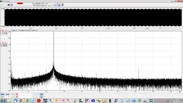
Hi bohrok2610 ... seems my earlier feedback post has disappeared - but anyway ... I had posted to say that your suggestion appears to have worked 🙂 The spectrum now looks like the attachment - still in no way perfect but I think it reflects what is going on - and is stable. ... many, many thanks for looking into this and posting the modified .inf file "sentence".
& also at this point a thanks to all of you for commenting & suggesting. I likely would not easily have thought of this without your additional discerning eyes and knowledge 😉
I will now turn my attention to the input driver circuitry which - as suggested by JensH - appears it may benefit from improvements.
Cheers,
Jesper
Attachments
I use DiAna single ended all the time. There is a setting to sync on the incoming wave. You can also use it with a notch filter for even more insight.
@1audio: Thanks for the info 😉 ... I will look a bit more into it.
Otherwise this is mainly a post to show some progress, should some of you be interested ... As you may have noticed the spectrum I posted yesterday was quite noisy and not really being satisfied with this today I tried to:
1. Disconnect everything including my laptop from the mains. And although all of the measurement devices were already floating - also relative to each other - the difference was significant. Much noise disappeared.
2. Since I use a balanced input circuitry to the ADCs I have been wondering if the ~600 ohm output impedance from Victor's oscillator could have an influence on the ADC's response. So I inserted a variable resistor in the GND path from the oscillator and this also improved the response. However, the actual value of this resistor was not too critical. From ~ 540 - 620 ohms did not make that much of a difference.
3. Compare the AK5394 with the AK5572 in the same setup. And although the differences currently are not that huge it looks as if the overall noise level is ~5 - 7 dBs lower on the AK5394 whereas the distortion is ~ 5 dB lower on the AK5572.
I would have liked to post some screen dumps of the two ADCs' spectra, but apparently the AK5394 spectrum has been erased 😎 So the attached distortion spectrum is from the AK5572 - and in this context the AK5394 was just about 5 dB worse yet with a very similar overall response (The first screen dump is the AK5394 with inputs shorted (including input circuitry) & the second is the AK5572 spectrum. 2H is now at - 124 dB & 3H is at ~ - 115 dB (- 1 dB input level). 12 kHz sine wave).
Next up is improving the input circuitry for the AK5394. One key criteria here is a relatively high input impedance - both for single ended and balanced inputs. To this end I have been simulating a circuitry like the attached one - which simulates to have a very low distortion. It uses the output stage suggested by JensH and the input stage that I already use - so it would be convenient.
A couple of potential "issues" though:
- it looks as if the noise level at the output may be relatively high (sims at 7.5 nV/Hz) and thus it might not take advantage of the AK5394's low noise level. Am I right in thinking so - or do you think the noise level would be fine?
- I used the LT1028 for convenience in the simulation but I don't consider it very low distortion ... JensH has mentioned the LME49990 as a low distortion choice, however, IME it is a bit difficult to source these days. I could use the AD797s I already use but if there are lower distortion alternatives I would appreciate a hint on this, if you have any experiences here ...
Also, in general any comments on why - or maybe why not - this circuitry may work well would be appreciated.
Wishing you a pleasant day 😉
Jesper
Attachments

- Home
- Design & Build
- Equipment & Tools
- AK5394 input circuitry woes ...