Hi guys,
Interested at this high value / cost dual AK4493 AK4118 dac HIFI Dual AK4493EQ DSD DAC Bluetooth 5.0 Wireless Player AK4493 DAC XMOS Amanero USB LME49720 OPAMP OLED Display|Amplifier| - AliExpress
It looks that output stage Is done paralleling same phases and then summing In diferential op amp for every chip / channel and then to electrolytic to output
Would you please advise about using alternative output stage, just like nihtila for each chip / channel http://nihtila.com/wp-content/uploads/2020/02/W-DAC_v13B_sch_outputs.png
That way electrolytic Is eliminated and there are also true balanced output
Have a look at this paper:
https://www.hypex.nl/img/upload/doc/an_wp/WP_The_G_word.pdf
Bruno describes how to grounding works, but he also has a demo preamplifier in there. The preamplifier shows a great way of removing DC offset and how to work with differential amplifiers. While Nihtala's output stage works and has great performance, it also uses twice as many opamps as you actually need!
Personally I recommend using a MFB filter instead of sallen-key, because it's much easier to convert to differential (because the opamp input is grounded). After filtering you can just make a summing amplifier and use the DC offset circuitry from Bruno.
I've explained my solution in earlier comments. I won't publicly share mine at the moment. Perhaps that will change later.
ak4493 is voltage output dac. For DSD we need LPS at output what if i use only pcm?
What if we do not use opamp buffer at the end of output of AK4493. And directly feed amplifier?
What if we do not use opamp buffer at the end of output of AK4493. And directly feed amplifier?
Hi,
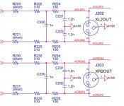
The XLR outputs are wired wrong. I recommend you read the paper by bruno putzeys about getting your audio off the ground. You'll realise why it's a mistake!
I'm not sure what the maximum output current is of the 4493 DAC. Lower resistor values = lower noise, but also higher load for the DAC (high current draw leads to distortion). Though it looks fine to me.
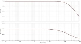
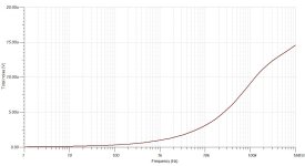
I would also simulate it in TINA TI or LTspice or something among the likes. They will tell you whether it does what you expect it to do. Sorry I am not going to calculate the Fc and Q of the filters. I'm a bit lazy (read busy with other things) today. My filter has a Fc of ~100k and a Q of 0.5. A low Q is essential for goot transient response.
Also I would ground the signal reference somewhere close to the decoupling capacitors of the opamps.
The XLR outputs are wired wrong. I recommend you read the paper by bruno putzeys about getting your audio off the ground. You'll realise why it's a mistake!
I'm not sure what the maximum output current is of the 4493 DAC. Lower resistor values = lower noise, but also higher load for the DAC (high current draw leads to distortion). Though it looks fine to me.
I would also simulate it in TINA TI or LTspice or something among the likes. They will tell you whether it does what you expect it to do. Sorry I am not going to calculate the Fc and Q of the filters. I'm a bit lazy (read busy with other things) today. My filter has a Fc of ~100k and a Q of 0.5. A low Q is essential for goot transient response.
Also I would ground the signal reference somewhere close to the decoupling capacitors of the opamps.
thank you for Input
first stage fc Is around 330 kHz and Q bellow 0.5, same for balanced to single ended differential op amp
I will try to do research In getting audio off the ground even though I am curious about what would bring
what Is curent status of your AK4493 setup - do you use dual mono dacs, type of audio output, power supply
how does sound
Hi samoloko
Your diagram looks fine for the output stage. You can always change values on the capacitors and resistors when you have build.
When you first have it in place, then you can in 99% case use the same schematic of the output for the AK4490, AK4495 and AK4497 with no modification.
- Sonny
Your diagram looks fine for the output stage. You can always change values on the capacitors and resistors when you have build.
When you first have it in place, then you can in 99% case use the same schematic of the output for the AK4490, AK4495 and AK4497 with no modification.
- Sonny
thank you
that Is Idea - standart output for voltage out dacs using simple way (without Injecting ref voltages or caps) and low number op amps
I like to use to upgrade dual AK4493 dac http://go.diyaudio.com/?id=69111X15...37b43f3533c737&xjsf=other_click__auxclick [2]
that Is Idea - standart output for voltage out dacs using simple way (without Injecting ref voltages or caps) and low number op amps
I like to use to upgrade dual AK4493 dac http://go.diyaudio.com/?id=69111X15...37b43f3533c737&xjsf=other_click__auxclick [2]
samoloko,
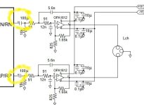
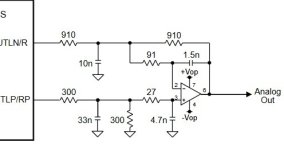
From your schematic a few posts up, looks like you have decided that much more filtering is needed for the unbalnaced outputs than for the balanced ones. That doesn't seem quite right to me. Last time I looked, ESS and AKM were both doing very similar things to add some passive filtering to unbalanced outputs after the first opamp stage. For one example, please see the attached schematic below.
Also, for the AK4499 eval board the passive filter caps appear to be SMD film and the resistors are through-hole, similar looking to Dale resistors (e.g. RN65) sometimes favored for hi-fi audio.
Attachments
Last edited:
thank you for Input
first stage fc Is around 330 kHz and Q bellow 0.5, same for balanced to single ended differential op amp
I will try to do research In getting audio off the ground even though I am curious about what would bring
what Is curent status of your AK4493 setup - do you use dual mono dacs, type of audio output, power supply
how does sound
Actually, I read the schematic wrong. I didn't realise you were going for dual mono. The XLR is wired correctly then. The document about getting your audio off the ground is still a fantastic read regardless though.
I'm not sure at what point the dac starts to become super noisy. The eval module uses a Fc of 100k hence I use the same.
I would try to put the RCA output after the XLR output. Otherwise your outputs are loaded unevenly. It also lowers component count, because you need less capacitors 😉.
My current status is that the DAC project has been placed on hold until I have finished my DSP circuitry. In the meantime I have finished the waveguide and acoustics of the loudspeaker that the product is working for. My time has been very limited since my degree is taking MUCH more time than anticipated.
I also keep learning and tend to alter the design a lot :s
@Markw4
The ESS and AK4499 are current output DAC's and thus have a vastly different outputstage. The output stage recommended by AKM for the AK4493 is a non-balanced differential output stage. I wouldn't take their designs TOO seriously on this aspect.
As for filter caps I would highly recommend C0G/NP0 caps for their excellent linearity and low microphonics. For resistors I would use thin film resistors. Vishay makes excellent stuff, not always the cheapest. Though I rather spend 20 bucks more on a great product than have a generic product.
@hidjedewitje,
I agree that the first stage in the dacs I mentioned are I/V converters rather than differential summing multi-feedback filters. Since the is one more active pole in the latter first stage, residual RF from the dac outputs may be somewhat less (among other differences). My point was that one of the reasons SD dacs may not sound as good as they otherwise might is because of insufficient filtering of RF from the outputs. The RF may or may not cause issues in downstream equipment. If in fact there is remaining RF that needs filtering, which is suggested by samoloko's second stage for the unbalanced outputs, then there is probably also remaining RF that should be filtered from the balanced outputs. A passive filter offers 'real' poles and may produce less distortion in that position than an active filter might. Of course, everything depends on the particulars of a given dac chip and the surrounding implementation. Its up to the designer to figure out how much of what processing will be optimal for the project's design goals. 🙂
I agree that the first stage in the dacs I mentioned are I/V converters rather than differential summing multi-feedback filters. Since the is one more active pole in the latter first stage, residual RF from the dac outputs may be somewhat less (among other differences). My point was that one of the reasons SD dacs may not sound as good as they otherwise might is because of insufficient filtering of RF from the outputs. The RF may or may not cause issues in downstream equipment. If in fact there is remaining RF that needs filtering, which is suggested by samoloko's second stage for the unbalanced outputs, then there is probably also remaining RF that should be filtered from the balanced outputs. A passive filter offers 'real' poles and may produce less distortion in that position than an active filter might. Of course, everything depends on the particulars of a given dac chip and the surrounding implementation. Its up to the designer to figure out how much of what processing will be optimal for the project's design goals. 🙂
Last edited:
Not long ago I purchased this; BA-3 Bluetooth 5.0 Decoder AK4493 QCC3008 HIFI Audio Board MCK w/ Antenna | eBay
I installed it into a pristine BGW 250 amp I found. After a few weeks of running, and sounding good, I decided to swap the 47uf electrolytic caps that were in the power supply for the output filter.
Still haven’t found the true root cause, but the end result was a dead channel on my BGW amp, and a dac that has 14v of dc output, presumably from a dead 7915 regulator. Maybe the parts I used were too old, and should have been reformed before use, but I’ve never had anything like that happen before.
May try another one, but will wait and see if some other options appear in the meantime, (hopefully without ceramic caps in the output filter), and have temporarily abandoned that project at least until I replace the amp.
So the board sounded good, even with ceramic caps in the filter, however, I’m not entirely sure that it’s reliable, as the failure appeared to be somewhat intermittent.
Those caps are not needed. LPF can have high cutoff as there is a digital filter as well which has lower cutoff. The external LPF circuits in datasheet are not recommendations, only examples.
But I've measured DC at outputs and it is 2.5V to GND... Here is a topic with a similar question and here some quotes:
No it's not. That's why it should be biased to half of the positive rail. And that's why we need capacitor to block the DC at the output.
So, why coupling caps are not needed in this case I can't understandYou do understand that the capacitors are necessary for the circuit on page 24 to function correctly. The circuit in example 1 on page 23 is shown without capacitors because it does not need them. If you use the '1632 as shown on page 24 you will need the caps and if as shown on page 23 you will not.
Attachments
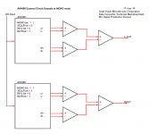
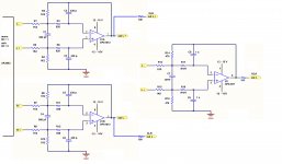
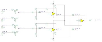
Witam, zaprojektowałem przedwzmacniacz do AK4493 mono. Jestem początkujący, więc proszę o swoją analizę i wszelkie możliwe sugestie. Nie mam pojęcia czy napięcia wejściowe są prawidłowe (2,8Vpp)? . VG3 i VG4 są przesunięte o 180 stopni. Z moich obliczeń fc=177075Hz i Q=0,49
 Translated:
Translated:Hello, I designed a preamplifier for the AK4493 mono. I'm a beginner, so please give me your analysis and any possible suggestions. I have no idea if the input voltages are correct (2.8Vpp)? . VG3 and VG4 are offset by 180 degrees. From my calculations fc=177075Hz and Q=0.49
Attachments
Last edited by a moderator:
sznobel
This is an English language forum only. I used Google translate to read your post. Google says the English translation is:
"...Hello, I designed a preamplifier for the AK4493 mono. I'm a beginner, so I'm asking for your analysis and any possible suggestions. I have no idea if the input voltages are correct (2.8Vpp)? . VG3 and VG4 are offset by 180 degrees. From my calculations fc=177075Hz a..."
Regarding your schematic, the circuit can't work properly. The output opamp feedback path will cause it to ignore the signal from the first opamp on top.
- Home
- Source & Line
- Digital Line Level
- AK4493 DAC