It is forbidden to put a capacitor from the output of a voltage amplifier to ground if you do not want problems.
I don't quite follow you there. Why is a capacitor to ground forbidden?
Is it because of the phase shift caused at higher frequencies and possibly creating 360 degrees?
Or is it perhaps the inrush current?
With a very large cap the current limitation of the op-amp will limit the voltage excursion to a level that can't generate oscillation but the problem remain and the noise problem that is mentioned above is a good example.
A L-C filter will have an effect in a much wider band than any shunt or LDO regulator.
If you know something more please do a demonstration (mathematically).
I am not saying it is a good idea. It's used by a lot of people following the ESS app note, for example, without noise problems to my knowledge. I don't really have the time or interest to investigate it mathematically as I wouldn't do it in the first place.
I am not saying it is a good idea. It's used by a lot of people following the ESS app note, for example, without noise problems to my knowledge. I don't really have the time or interest to investigate it mathematically as I wouldn't do it in the first place.
How would you solve this problem then? I'll look into it myself then when I get the time!
How would you solve this problem then? I'll look into it myself then when I get the time!
I'd use an LT3042 and be done with it 🙂.
I don't quite follow you there. Why is a capacitor to ground forbidden?
Is it because of the phase shift caused at higher frequencies and possibly creating 360 degrees?
Or is it perhaps the inrush current?
What you want to obtain punting a big capacitor at the output of an operational amplifier?
Can you explain?
A capacitor to ground it is used to filter the noise BUT the opamp it is put there to generate a CORRECTED signal that not need a capacitor to shunt to ground the noise. Finally the capacitor will shunt to ground most of the noise and the opamp will try to adjust the same thing.
Every body will try to do the same thing BUT their actions will be in opposite directions and will be neck to neck.
Anyhow, audiophile is a serious illness that likes to complicate unnecessarily.
Well the datasheet of the AK4493 states that a high capacitance on the VREF pin is recommended. I wanted to use a very stable voltage reference and came across the LTC6655 5V reference.
The LTC6655 doesn't like high currents or high capacitors. Diyaudio user Thorb showed me that manufacturers sometimes buffer the voltage reference. So I started looking for buffers. I am most comfortable with using opamps so I started looking there.
Now I am getting feedback that opamps are not recommended for this application. I do not understand why exactly.
Try with a resistor of 0.5-1ohm (maybe more) between LTC6655 output and capacitor.
The LTC will be harpy with this. I do not know about the DAC.
Personally I will use only a LC filter without the LTC.
The LTC will be harpy with this. I do not know about the DAC.
Personally I will use only a LC filter without the LTC.
Hi,
I use Studer900 boards for VDD
and 2200uF-35V - Vishay Série 136 RVI // WIMA FKP3 0.1uF-63V for VREF.
It's works very well !
With DIYINHK boards, the AK4493 version is much better than the AK4490 version.
nounouchet
I use Studer900 boards for VDD
and 2200uF-35V - Vishay Série 136 RVI // WIMA FKP3 0.1uF-63V for VREF.
It's works very well !
With DIYINHK boards, the AK4493 version is much better than the AK4490 version.
nounouchet
I also found some polymer capacitors, surprisingly good, even they are cheap. Their brand name is X-CON. I have used for AK4490 project 2 caps in parallel, 1200uF & 7mOhm ESR each, but they were redundant for this particular project, since I also used LT3042 for Vref.
Anyway, if AK4490 is so good - in my opinion is almost as good as AD1955 which is my favorite - , then I only can imagine how good are the newer AKM DAC chips, AK4493/97, not speaking about 99.
Anyway, if AK4490 is so good - in my opinion is almost as good as AD1955 which is my favorite - , then I only can imagine how good are the newer AKM DAC chips, AK4493/97, not speaking about 99.
Attachments
Well the datasheet of the AK4493 states that a high capacitance on the VREF pin is recommended. I wanted to use a very stable voltage reference and came across the LTC6655 5V reference.
The LTC6655 doesn't like high currents or high capacitors. Diyaudio user Thorb showed me that manufacturers sometimes buffer the voltage reference. So I started looking for buffers. I am most comfortable with using opamps so I started looking there.
Now I am getting feedback that opamps are not recommended for this application. I do not understand why exactly.
It is correct that the datasheet recommends using a large capacitor on the VREF pin.
But I think this is due to the fact that AKM still use a power supply, which is not state of the art in terms of noise. So they use series resistors (10 ohm) and large capacitors to reduce the noise. With small capacitors the impedance at low frequency is relatively high, leading to distortion. The large capacitors reduce the impedance seen on the VREF and thereby the distortion.
I don't think that the LTC6655 is a good choice for this application! It is quite noisy and you really don't need the accuracy or stability for music playback.
I have considered using it as reference for the AK4493, but together with the LT3042 and heavy filtering. But that was for use in an audio analyzer, where absolute accuracy and stability is important. For music playback I wouldn't bother.
I fully agree!I'd use an LT3042 and be done with it 🙂.
Hi!
The thread is quite old by now. I indeed decided to go the easy route and use a LT3042.
Mainly because of the measurements that Nihtala provided here:
Wee DAC update 3 – New LDO and AK4493 tests, and new boards designed – nihtila.com
Using an LT3042 reaches actually exceeds the datasheets level of performance. Linear Technologies states that the LT6655 lowers the 1/f noise. I figured that'd be benificial, however noise of the power supply is not the limiting factor here. And thus there is no reason to use and additional expensive chip.
Thanks for the help everyone though!
Hi
It's been a while. I actually had this project parked for quite long time in terms of AK4493 (just went forward with the AK4490 version) but as I've just got back to it in last two weeks, here is some update.
I got lots of issues with AK4493 version and got very frustrated. I saw performance peaking at -115 dB THD+N (or even -116 dB) but results were not consistent. My test board measurements were very promising I had posted here, but in the actual small form factor application PCB they were not. Or if I got one board working well, and made two more, results were all over the place.
One major difference in the test board was separate power supplies for all four VREFL, VREFR, VDDL, and VDDR. In my application board VREFL/VDDL and VREFR/VDDR shared regulators. Anyway, capacitors were the big headache. And a note here that this has been purely technical analysis from measurements perspective.
I've tried different sorts of caps: ceramics in different capacitance and case size, electrolytics, polyelectrolytics, polytantalums.. Some work better, some worse. Overall, with LT3042 I did not measure improvement when using large (hundreds or thousands of uF) electrolytics or tantalums; in fact performance often got worse. But I know some others have used them successfully.
The oddest thing was that just by moving a 100n or 10u ceramic from a placeholder to another (I have several onboard), in some cases THD+N swinged by 15 dB. I thought maybe there was something odd in my supply impedance and tried to carry out supply/plane impedance measurements. Learned a lot about that but unfortunately measurement conclusions were not so clear; maybe I just didn't measure it correctly.
Went back to trial and error method, just trying loads of caps and measuring audio performance. I did find a combination that gives solid and consistent -115 dB THD+N (around -121 dB THD) across five boards I used for tests. Not a huge sample size still but definitely a lot better and more consistent result than before.
Maybe there is something in my board that makes it so sensitive to the capacitance, I don't know. But it wasn't easy to find a solution with LT3042 and AK4493. With AK4490 I didn't have such issues when tried it.
I have attached some measurement results. Now THD+N vs level is straight line almost until maximum level. Also THD+N vs frequency is almost straight line which wasn't the case with some other LDOs I tried. You can find more measurements here W-DAC 4493 – Very high performance compact DAC – nihtila.com
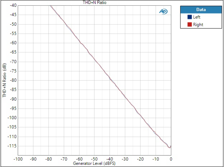
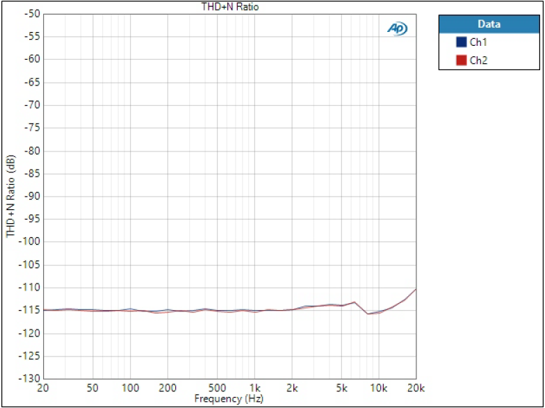
Oh yeah, the killer cap combination in this case? 10u ceramics directly at LDO output, then 2x 10u 0603 ceramics at VREF and 100n + 10u at VDD. No fancy large caps.
PS. I have also boards available if someone is interested.
It's been a while. I actually had this project parked for quite long time in terms of AK4493 (just went forward with the AK4490 version) but as I've just got back to it in last two weeks, here is some update.
I got lots of issues with AK4493 version and got very frustrated. I saw performance peaking at -115 dB THD+N (or even -116 dB) but results were not consistent. My test board measurements were very promising I had posted here, but in the actual small form factor application PCB they were not. Or if I got one board working well, and made two more, results were all over the place.
One major difference in the test board was separate power supplies for all four VREFL, VREFR, VDDL, and VDDR. In my application board VREFL/VDDL and VREFR/VDDR shared regulators. Anyway, capacitors were the big headache. And a note here that this has been purely technical analysis from measurements perspective.
I've tried different sorts of caps: ceramics in different capacitance and case size, electrolytics, polyelectrolytics, polytantalums.. Some work better, some worse. Overall, with LT3042 I did not measure improvement when using large (hundreds or thousands of uF) electrolytics or tantalums; in fact performance often got worse. But I know some others have used them successfully.
The oddest thing was that just by moving a 100n or 10u ceramic from a placeholder to another (I have several onboard), in some cases THD+N swinged by 15 dB. I thought maybe there was something odd in my supply impedance and tried to carry out supply/plane impedance measurements. Learned a lot about that but unfortunately measurement conclusions were not so clear; maybe I just didn't measure it correctly.
Went back to trial and error method, just trying loads of caps and measuring audio performance. I did find a combination that gives solid and consistent -115 dB THD+N (around -121 dB THD) across five boards I used for tests. Not a huge sample size still but definitely a lot better and more consistent result than before.
Maybe there is something in my board that makes it so sensitive to the capacitance, I don't know. But it wasn't easy to find a solution with LT3042 and AK4493. With AK4490 I didn't have such issues when tried it.
I have attached some measurement results. Now THD+N vs level is straight line almost until maximum level. Also THD+N vs frequency is almost straight line which wasn't the case with some other LDOs I tried. You can find more measurements here W-DAC 4493 – Very high performance compact DAC – nihtila.com
Oh yeah, the killer cap combination in this case? 10u ceramics directly at LDO output, then 2x 10u 0603 ceramics at VREF and 100n + 10u at VDD. No fancy large caps.
PS. I have also boards available if someone is interested.
The capacitance on ceramics of such small value changes drasticly based upon dc bias. Have you taken that in to account.
By the way, I checked out your website and it has been very helpful. Thanks a lot for the research!
By the way, I checked out your website and it has been very helpful. Thanks a lot for the research!
The capacitance on ceramics of such small value changes drasticly based upon dc bias. Have you taken that in to account.
By the way, I checked out your website and it has been very helpful. Thanks a lot for the research!
Thanks!
I am aware of capacitance being significantly less when DC-biased. Although not really overly worried about it in this application. There's a lot in capacitors to consider. Not only capacitance but also ESR and inductance (and how things may change across voltage, temperature etc). And when you have several capacitors in parallel, effectively it becomes a complex LRC network (and add there the PCB, LDO/source and DAC/load). I hoped my supply impedance measurements would have revealed something in there but unfortunately I think I was mostly measuring the limitations of my measurement setup which is always a possible issue in measurements. Need to experiment more some day.
So it's unlikely this is just about the capacitance; more was not really better in this case. Although capacitance reduction due to biasing is good to keep in mind especially when thinking of minimum capacitances for LDO outputs. Especially when going into smaller case sizes such as 10u 0603 I've used here, the real capacitance is only a fraction of that.
The LT3042 and AK4493 are both excellent chips. I don't think the problem lies there. I assume the problem lies within the implementation/integration between the two chips.
I think there is some kind of resonance in the output circuitry of the LT3042. Personally I like putting a snubber network next to the output capacitor. It reduces the resonance caused by the "inductive" output impedance.
I also noticed in your schematic that you don't use ferrite beads in the supply line. I really like to use those in addition to decoupling capacitors. They don't cause resonances in practice because they generally behave lossy at higher frequencies.
Have you experimented with the capacitor across the reference resistor of the LT3042? My dac will be placed in a DSP loudspeaker so the microphonics of the ceramic capacitors might become relevant (as it's not within the control loop of the LT3042). Would you think a film is appropriate here? They are quite expensive after all.
Also a bit off topic:
Your output stage uses 2 opamps (U1 and U2) to make one differential amplifier. An opamp is by nature a differential amplifier and you could use one! It would save you an opamp or leave budget for more premium opamps (though the 4562 is amazing already). Mr. Putzeys greatly explains how in this publication: https://www.diyaudio.com/archive/bl...d1460406090-bruno-putzeys-micropre-g-word.pdf
The LT3042 and AK4493 are both excellent chips. I don't think the problem lies there. I assume the problem lies within the implementation/integration between the two chips.
I think there is some kind of resonance in the output circuitry of the LT3042. Personally I like putting a snubber network next to the output capacitor. It reduces the resonance caused by the "inductive" output impedance.
That's why I tried to measure power supply/plane impedance to see possible resonances but couldn't. That doesn't mean they're not there but I couldn't measure them; it's quite tricky to measure in MHz range and over although DAC sampling frequency (probably around 3Mhz or 6MHz) could be useful. Then you could try to tackle them by adding snubbers or changing cap types. After all, you should know what the snubber is there to do instead of randomly picking components.
I also noticed in your schematic that you don't use ferrite beads in the supply line. I really like to use those in addition to decoupling capacitors. They don't cause resonances in practice because they generally behave lossy at higher frequencies.
Where would you expect to see them? I do use ferrites in some circuits where supply lines come onboard, or before regulators. But I don't like to put them anymore after regulators. Yes, could add a placeholder but then I cannot tie LDO output so well to power plane or fill anymore. Would they help close to IC pin before C, or would they make it worse, I don't know. Ferrites work mostly in quite high frequencies.
Have you experimented with the capacitor across the reference resistor of the LT3042? My dac will be placed in a DSP loudspeaker so the microphonics of the ceramic capacitors might become relevant (as it's not within the control loop of the LT3042). Would you think a film is appropriate here? They are quite expensive after all.
I wouldn't be worried but I have no experience what microphonics can cause. Of course if you're worried you can use non-ceramic, and also smaller value if it becomes too large or expensive but then it increases output noise. I believe it is quite important cap so maybe you could use something better here.
Also a bit off topic:
Your output stage uses 2 opamps (U1 and U2) to make one differential amplifier. An opamp is by nature a differential amplifier and you could use one! It would save you an opamp or leave budget for more premium opamps (though the 4562 is amazing already). Mr. Putzeys greatly explains how in this publication: https://www.diyaudio.com/archive/bl...d1460406090-bruno-putzeys-micropre-g-word.pdf
I totally agree! I have used such circuits and even made my own version of Putzey's preamp. The problem is that people don't want such outputs; maybe they don't understand it? I've had boards where I offer this sort of impedance balance or hot/cold both actively driven, and no-one picks the former. Of course, the price difference is very small with opamps like LM4562, so maybe it would be more of a choice if the opamp was very expensive.
That's why I tried to measure power supply/plane impedance to see possible resonances but couldn't. That doesn't mean they're not there but I couldn't measure them; it's quite tricky to measure in MHz range and over although DAC sampling frequency (probably around 3Mhz or 6MHz) could be useful. Then you could try to tackle them by adding snubbers or changing cap types. After all, you should know what the snubber is there to do instead of randomly picking components.
Ideally you have no AC current running through the ground plane because the groundplane is highly inductive (and this doesn't change significantly with thickness). Having high AC current running through the groundplane will thus create relatively high emissions and since the groundplane is also the return path for the signal it can cause common impedance coupling.You could measure the AC current flowing through the groundplane near the DAC.
Decoupling capacitors short the RF current to prevent it from going through our circuit and they also make the current loop very small (which is why they should be placed close to the IC).
Decoupling capacitors however don't reduce the RF current, ferrite beads on the other hand do! Ferrites are also lossy (become resistive) at high frequencies. This will prevent them from becoming a high Q LC circuit.
The LT3042 is an outstanding regulator and does quite good up to a few MHz, but afterwards L's and C's are much more effective.
I like to use Guido Tent's (of Grimm audio and Tentlabs) approach for decoupling. It can be found here:
http://members.chello.nl/~m.heijligers/DAChtml/Supply_decoupling.pdf
I also have the slides of his AES presentation about power supplies. Which has some useful info about linearizing the output impedance of voltage regulators.
I wouldn't be worried but I have no experience what microphonics can cause. Of course if you're worried you can use non-ceramic, and also smaller value if it becomes too large or expensive but then it increases output noise. I believe it is quite important cap so maybe you could use something better here.
Dave Jones (of EEVblog) noticed microphonics in probes or input stage of this R&S oscilloscope. The order is about a couple of mV.
YouTube
I think I will do a footprint that will fit both a ceramic and film capacitor.
I totally agree! I have used such circuits and even made my own version of Putzey's preamp. The problem is that people don't want such outputs; maybe they don't understand it? I've had boards where I offer this sort of impedance balance or hot/cold both actively driven, and no-one picks the former. Of course, the price difference is very small with opamps like LM4562, so maybe it would be more of a choice if the opamp was very expensive.
I will make my own version of his preamp. I'll use a switched relay attenuator though (I want digital control and relay seems to be the best performing).
Luckily we are in the DIY world where you can make whatever you want 😉. There's always clever people, like Bruno and yourself, that are willing to help others by publishing their research.
This maybe gets a bit off-topic but as it's interesting and still relevant topic, and I also want to learn as much as possible I will continue a bit.
I agree with the PDF you've linked, at least mostly, although it seems it was written a long time ago. Physical scales are a lot smaller now, but so are frequencies higher. It mentions decoupling cap to IC trace lengths as 2cm but for example mine are closer to 2mm. I'm also not sure how likely these large loops are to form, after all the current will choose the lowest impedance paths. But true, there will be some resonances.
I did use similar ferrite placements when my boards were 2-layer. Now I mostly use 4-layer boards (at least for mixed signal audio) and don't see it as necessary anymore; although still use in some points.
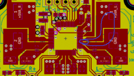
Let's see my board, pic attached. I've drawn a loop for the closest ceramic decoupling cap and for large electrolytic (if it was used). As can be seen, these current loops are not in the planes but on local top layer traces. The group of four vias you see are then connected to ground plane and power plane. I guess if I wanted to use a ferrite, this point would be suitable. But even like this the loops should remain local.
Even if the return currents would be on planes, it's unlikely they would cause much issues for audio signals as they are differential. But of course minimising loop area and keeping them as local as possible is one of the main PCB design guidelines.
Btw, that's exactly what I did as well regarding Bruno's preamp. I combined his preamp idea with Hans Polaks relay attenuator. I just had some odd crosstalk issues with the design and I never debugged it properly. It's something I will probably go back at some point this year. But the amp is in use in my headphone setup.
I agree with the PDF you've linked, at least mostly, although it seems it was written a long time ago. Physical scales are a lot smaller now, but so are frequencies higher. It mentions decoupling cap to IC trace lengths as 2cm but for example mine are closer to 2mm. I'm also not sure how likely these large loops are to form, after all the current will choose the lowest impedance paths. But true, there will be some resonances.
I did use similar ferrite placements when my boards were 2-layer. Now I mostly use 4-layer boards (at least for mixed signal audio) and don't see it as necessary anymore; although still use in some points.
Let's see my board, pic attached. I've drawn a loop for the closest ceramic decoupling cap and for large electrolytic (if it was used). As can be seen, these current loops are not in the planes but on local top layer traces. The group of four vias you see are then connected to ground plane and power plane. I guess if I wanted to use a ferrite, this point would be suitable. But even like this the loops should remain local.
Even if the return currents would be on planes, it's unlikely they would cause much issues for audio signals as they are differential. But of course minimising loop area and keeping them as local as possible is one of the main PCB design guidelines.
Btw, that's exactly what I did as well regarding Bruno's preamp. I combined his preamp idea with Hans Polaks relay attenuator. I just had some odd crosstalk issues with the design and I never debugged it properly. It's something I will probably go back at some point this year. But the amp is in use in my headphone setup.
Attachments
I agree with the PDF you've linked, at least mostly, although it seems it was written a long time ago. Physical scales are a lot smaller now, but so are frequencies higher. It mentions decoupling cap to IC trace lengths as 2cm but for example mine are closer to 2mm. I'm also not sure how likely these large loops are to form, after all the current will choose the lowest impedance paths. But true, there will be some resonances.
It certainly is quite old. Guido wrote it in the late 90ies for philips (as stated in the document). Physics don't change though. Technologies do though.
I don't really look at the actual numbers. They do seem outdated.
The point is that we now know how to use ferrites and how to lay out our circuitry with proper emc performance and the document explains it well in my opinion.
Proper EMC doesn't require ferrite beads on every line. It's just at levels of -115dB, many things become relevant. I'm rather safe than sorry in this case. Especially since ferrites are cheap cheap.
Grimm's masterclock (CC1) also does use ferrites for every IC. As can be seen as these product photo's:荷兰原装进口格林 Grimm Audio CC1 母带级数字时钟_音源系列_广州阔景影音 - HiFi音响,家庭影院,单枪/三枪投影机,音响发烧站 - 音响贵族网
I would lay the ferrites out in a similar manner as they do in the CC1, except I would probably put every other ferrite 90 degrees rotated (so that the ferrite of the chip next to it is orthogonal). This could prevent magnetic coupling though it's probably excessive.
Let's see my board, pic attached. I've drawn a loop for the closest ceramic decoupling cap and for large electrolytic (if it was used). As can be seen, these current loops are not in the planes but on local top layer traces. The group of four vias you see are then connected to ground plane and power plane. I guess if I wanted to use a ferrite, this point would be suitable. But even like this the loops should remain local.
I wouldn't both with such a big electrolytic. The largest current the dac consumes is 50mA on the VDDL/R. The LT3042 or any other proper regulator should be able to do that if you have good decoupling techniques.
I would also place the via's near the close decoupling capacitor. It makes the current loop much smaller. As I said before, at -115dB strange things start to become relevant. Moving the via's might be a solution that comes free of charge!
Even if the return currents would be on planes, it's unlikely they would cause much issues for audio signals as they are differential. But of course minimising loop area and keeping them as local as possible is one of the main PCB design guidelines.
You assume here that all stages are perfectly balanced. An impedance imalance of 1-5% isn't strange. We also don't know how the dac itself operates internally. Maybe it's two single ended dac's with a differential outputstage.
Personally I think it's better to prevent the problem at all. Especially at the cost of 10 ferrite beads (or whatever amount of power supplies you use).
As for my relay attenuator:
Here's my first design:
An externally hosted image should be here but it was not working when we last tested it.
I'll be using it with the DRV777 IC by TI. It has internal protection diodes and allows MCU input. It's also part of the reason I use 7 Bit (which is an extreme amount!). It's based on this project except mine is balanced and uses a different digital circuitry:
RelaiXedPassive -- Documentation
I wouldn't both with such a big electrolytic. The largest current the dac consumes is 50mA on the VDDL/R. The LT3042 or any other proper regulator should be able to do that if you have good decoupling techniques.
Electrolytics are part of decoupling techniques. They help in supply impedance especially in mid frequencies, and losses of electrolytics may be useful as well (although such large have low ESR). LDOs like LT3042 themselves can push the impedance low in those frequencies so it may not bring much extra. And that is the case here, and that's why the large electrolytics are not populated with LT3042. However, the difference in supply impedance is clearly measurable.
I would also place the via's near the close decoupling capacitor. It makes the current loop much smaller. As I said before, at -115dB strange things start to become relevant. Moving the via's might be a solution that comes free of charge!
Vias are not part of (AC) current loops between IC and decoupling. They are deliberately kept out of the current loops formed through decoupling caps. Think of them similar to your ferrite beads in terms of placement here - and they do have small inductance as well.
- Home
- Source & Line
- Digital Line Level
- AK4493 DAC