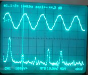
Comparison for AK4490 at 192kHz SR (quad), fs/4 signal, Slow vs. NOS filter, MCLK 24.5MHz.
"Slow" results in 8 segment per cycle, NOS in 4. H3 and and H5 are well reduced. The difference to NOS is some 30dB.
This suggests that an (external) working FIR at oct/hex rates would achieve similar amounts of reduction of H3 and H5, making life easier for the analog filter. AKMs can run external filters, too...
Attachments
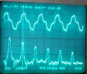
Comparison for AK4490 at 192kHz SR (quad), fs/4 signal, Slow vs. NOS filter, MCLK 24.5MHz.
"Slow" results in 8 segment per cycle, NOS in 4. H3 and and H5 are well reduced. The difference to NOS is some 30dB.
This suggests that an (external) working FIR at oct/hex rates would achieve similar amounts of reduction of H3 and H5, making life easier for the analog filter. AKMs can run external filters, too...
Yes, you can run an external filter with the AK4490/3 also. I had thought it was limited to AK4499 for some reason. Too bad it doesn't support > 768 kHz input in that mode, though. You can do 1.536 MHz with the Sabres. I thought you could also with PCM179x but it may be limited to 768 kHz also.
I did make an unfair comparison, but the behavior at oct/hex mode with the "internal filter" looks like what I would expect to happen if you fed PCM179x unfiltered data at 384 kHz or 768 kHz via the external filter mode. I feel like it's dishonest to not mention that the filter is non-existent above 192 kHz. Maybe ESS does this too, I don't know. Cirrus and TI are honest with the graphs/notes they publish at 384 kHz as in the CS43198 datasheet and PCM5122 datasheet. Using AKM's criteria, TI should have been selling PCM179x as supporting 768 kHz all along 😉.
I guess I was just naive to think they left the filter specs out of the datasheet because they were bad, not because it's bypassed in those modes.
Last edited:
Has no one tested ES90xx or the AK4499 at these rates?
ES9038Q2M is next to AK4493 on my board, a few days...
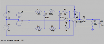
I had great success with a passive 4 pole L/C filter on the output of an AK4490 DAC. I have long been suspicious of using an active analog filter to filter in a band where its loop gain is rapidly approaching zero. The ferrite inductors from coilcraft worked fine, did not add measurable distortion and had a nice small footprint. It removed the image above the sampling frequency to much better than 80 dB. The analog filter on the demo board did not.
Attachments
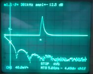
ES9038Q2M, 768kHz fs, MCLK fsx128 = 89MHz, brickwall filter. Sine 350kHz, probed directly at the chip output, no analog filter. That does not look like a "refurbished" 192kHz chip 🙂
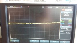
At fs 855kHz (MCLK 106MHz) the output is already broken, as specified in the datasheet (MCLK max 100MHz).
At fs 855kHz (MCLK 106MHz) the output is already broken, as specified in the datasheet (MCLK max 100MHz).
Attachments

Well, this is a bit easier to filter out 🙂 But I have not measured wide-band noise performance, that will take some time.
The ES9038Q2M measurement looks very good.
What does the second figure show? Is it a zoomed view of the first one?
Have you measured the frequency response or at least cheched at a few points that it is flat?
I assume by the way, that you mean MCLK = 98 MHz, not 89 MHz.
What does the second figure show? Is it a zoomed view of the first one?
Have you measured the frequency response or at least cheched at a few points that it is flat?
I assume by the way, that you mean MCLK = 98 MHz, not 89 MHz.
Last edited:
Those steps are probably sampling of my digital scope. Visually I could not identify any steps at slower time base. Wideband spectrum measurement would probably show some. IIRC IVX measured some stronger MCLK content which would be perfectly fine at 128xFS.
What does the second figure show? Is it a zoomed view of the first one?
It should have been analog to pictures in https://www.diyaudio.com/forums/equ...-oversampling-filter-issue-4.html#post6659154 but see my previous post.
Have you measured the frequency response or at least cheched at a few points that it is flat?
Not yet. I went closer to fs/2 where the brickwall filter started affecting amplitude (correctly). But the waveform was still correct, the brickwall filter works OK.
I assume by the way, that you mean MCLK = 98 MHz, not 89 MHz.
Yes, thanks for the correction. 768kHz * 128 = 98.3MHz. The cause: I had my calculator switched to hexadecimal 🙂
Last edited:
Pavel, can you measure impulse response (with train of dirac feed) and plot FFT of it with your DSO, with averaging?
Last edited:
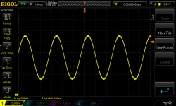
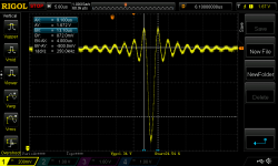
Unfortunately the FFT of my Rigol is unusable, min. bin width 100kHz, max 1MHz. Dirac pulse (1sample, -3dB, brickwall filter) at 768kHz attached.
Attachments
Last edited:
Now that looks very good! No FFT needed.
Does this suggest that the ESS FIR is operating at DS-modulator frequency, or at least they don't use a S/H at the DS input? I think so.
In the dirac output of the 4490 I can see 16 steps which would match the 16x S/H stage as known from the 439x internal diagram.
Does this suggest that the ESS FIR is operating at DS-modulator frequency, or at least they don't use a S/H at the DS input? I think so.
In the dirac output of the 4490 I can see 16 steps which would match the 16x S/H stage as known from the 439x internal diagram.
IMO their digital part runs at MCLK. 100MHz is not a major frequency for digital processing these days, every second MCU for 1 dollar runs faster. I guess the real problem is making the DS modulator perform well at such frequencies.

The I/V stage and filter should run tomorrow, if no problems arise. A measurement with a decent 4GSps scope could ensue...
It for sure will beat this ;-)
At these pulse lengths the SC-filter is still integrating and hence the waveform is more like linear interpolation than Dirac-delta which helps spectrum.
You cursor readout shows 1.5 periods, so actual sinc freq. is more like 250Khz*1.5=375kHz and the shape suggests true brickwalling. Quite a difference.
Attachments
Now that looks very good! No FFT needed.
Does this suggest that the ESS FIR is operating at DS-modulator frequency, or at least they don't use a S/H at the DS input? I think so.
In the dirac output of the 4490 I can see 16 steps which would match the 16x S/H stage as known from the 439x internal diagram.
The ASRC is integral to the design, so I suppose it makes sense that their filters work at the output rate. I wonder if it behaves the same if you run it in synchronous mode.
The ESS was switched to synchronous, no ASRC. Hence the fixed multiple MCLK = 128xFS for any FS.
- Home
- Design & Build
- Equipment & Tools
- AK4493 at oct/hex sampling speeds - oversampling filter issue?