Hi All,
I'm interested in learning something about audio circuit design. The ultimate goal of this project is to discuss/learn about various supporting circuits for the design of a decent measuring/(hopefully good sounding) DAC. I'm hoping all you experts out there can give some/lots of pointers! The second goal of this design is to develop my own DAC to be used in my semi from scratch sound system if design proves at least somewhat successful.
Since using AKM device, might as well keep it in the family. Modules to be included in a custom enclosure:
1. Receiver Module, SPDIF/TOSLINK or other I2S.
2. By-passable SRC converter using AK4137EQ.
3. DAC module based on AK4490EQ.
I'd like to start with the AK4490EQ module:
Design goals:
- Stand-alone operation with I2S inputs fed from AK4137EQ/AK4115 or similar devices.
- On-board regulators. Willing to sacrifice a bit of board space for this. Allow pads for use of external regulator if I muck something up.
- All power supply and output stage buffering to be included on-board. Allow pads for use of external buffers if I muck something up.
- The rest keep as simple as possible. I think running in stereo mode is easiest. Could run 2 modules if MONO mode is desired.
- Keep board as small as possible but do not sacrifice design for this.
- IC cost is not a prime issue.
I'm a little fuzzy on I2S protocol workings so I will have to do some reading. As a starting point, I wish to use linear regulators which drop voltage from a reasonable power supply. Targeting toroidal type source but willing to entertain other options if there is a good case for lower measured noise from this source and/or the filtering demands do not get out of hand.
Lets start the discussion off with the AK4490 power supply and VRef circuits, AVDD, DVDD and VREF. Linear regulator choices......I've used "TPS7A4700" and "TPS7A3301" before and know they work. They are small and have a wide input voltage range. Separate regulators will be used for AVDD, DVDD and VREF. Other suggestions?
For VREFR/L is there any benefit to using a low noise op-amp vs the adjustable low noise linear regulators suggested above? The AK4490 evaluation design uses AD817 for these supplies. Perhaps absolute level regulation by feedback resistor tuning is a pain? Perhaps a voltage reference and low noise op-amp inverter will work just as well? I guess this has output voltage implications as too.
Lastly, I apologise if these concepts have been covered elsewhere. I've done a quick search but it is a large board. Links to the correct threads are welcome🙂
Last edited:
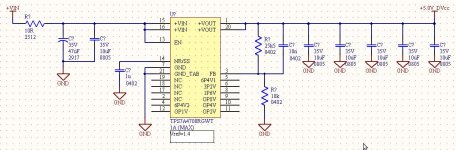
Ok Linear Regulator Circuit is straight forward. Attached. Decided to use 4 separate regulators for AVDD, DVDD, VREFR and VREFL as per AK4490 reference design. SMT parts and layout close will be close to TPS7A4700 reference board.
Any suggestions for VREFR/L supplies are welcome.
+VIN will come from a regulated supply as per Rod Elliot low power "super regulator" topology. Input supply around 7-10V filtered DC.
Suggestions for I2S header is also welcome. Probably go with 0.1" header unless there are valid technical reasons to change.
Attachments
Last edited:
Hi, interesting thread, subbed!
You may consider using inductors in your project. I have found lately a great document about decoupling and design of PCB, PM me your mail and I'll send it to you! 🙂 I'm not entirely sure if independent supplies for VREF are really needed, they might not be worth the money and work, probably, just feeding them from AVDD through pi filter is going to be enought.
You may consider using inductors in your project. I have found lately a great document about decoupling and design of PCB, PM me your mail and I'll send it to you! 🙂 I'm not entirely sure if independent supplies for VREF are really needed, they might not be worth the money and work, probably, just feeding them from AVDD through pi filter is going to be enought.
Thanks for the suggestions SomekPoland. Looks like the ADM7150 is pretty good for this application. Attached is the new PS schematic. Also it is starting to look like a passive filter between VDDR and VREF will do the job (also your suggestion).
So now thinking is separate Regulators for DVDD, AVDD, VDDR and VDDL. Passive filter from VDDR to VREFR, passive filter from VDDL to VREFL. Eval kit mentions a 2200uF cap between VREF pins can reduce low frequency distortion.
So now thinking is separate Regulators for DVDD, AVDD, VDDR and VDDL. Passive filter from VDDR to VREFR, passive filter from VDDL to VREFL. Eval kit mentions a 2200uF cap between VREF pins can reduce low frequency distortion.
Attachments

I'm interested in a slight variation of your proposed project - one that has spdif input, ASRC, and spdif output. Is there any chance that you could add an (optional) DIT to provide the spdif out?
Hi Charlie,
I hadn't planned on that route but the boards may be more flexible that way. I can see the application, good suggestion. I'll look into it.
Mike
I hadn't planned on that route but the boards may be more flexible that way. I can see the application, good suggestion. I'll look into it.
Mike
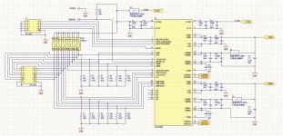
Barely legible but below is first crack at AK4490EQ main workings (output filters excluded). Any comments regarding de-coupling and overall workings of the IC are welcome.
Regarding connectors, current thinking is ribbon cable for the digital lines. For PCM this should be ok, but does anyone have any experience running the DSD lines via ribbon cable? Anyone have alternative transmission/connector suggestions for the DSD high-speed clock/data lines?
Thanks,
Regarding connectors, current thinking is ribbon cable for the digital lines. For PCM this should be ok, but does anyone have any experience running the DSD lines via ribbon cable? Anyone have alternative transmission/connector suggestions for the DSD high-speed clock/data lines?
Thanks,
Attachments
If you plan on "high" speed digital with DSD for instance ribbon cable is likely fine if you alternate ground and signal lines on the ribbon. For "low" speed digital I2S I can get away with only one ground per group.
The image you posted is barely legible on account of the resolution and the fact that the placement grid dots are showing. Can you remove the grid and upload at a little higher res?
The image you posted is barely legible on account of the resolution and the fact that the placement grid dots are showing. Can you remove the grid and upload at a little higher res?
With a 32 bit convertor I would think of your task as a high precision digital/analogue design.
IMHO you would get better signal integrity and avoid a lot of problems if you could have one board
instead of two connected by ribbon cable. All those headers and connectors are going to add impedance mismatches to some quite critical signals,
this could lead to SI problems especially with clocks. The bare minimum if you must use a connecting cable is
GND/SIG/GND/SIG etc, some newer 0.5 FFC/FPC type cables might be better.
4th picture down shows these for reference...
6moons audio reviews: Lindemann Audio musicbook:15 and musicbook:50
I would recommend a 4 layer board for this design, data sheet looks a bit confusing regarding the ground plane
I would use one contiguous ground with careful component placement then have some strategic slits near the convertor.
http://www.hottconsultants.com/pdf_files/june2001pcd_mixedsignal.pdf
http://www.x2y.com/filters/TechDay0...log_Designs_Demand_GoodPCBLayouts _JohnWu.pdf
http://www.ti.com/lit/an/slyt499/slyt499.pdf
http://www.ti.com/lit/an/slyt512/slyt512.pdf
http://www.analog.com/static/imported-files/tutorials/MT-031.pdf
http://www.ti.com/lit/an/slyt498/slyt498.pdf
The attached text file has a series of generic PCB design related links...
Attachments
Hi Guys,
Thanks for the info! Will look into it further.
Attached is a .pdf. Seems like it was the only way to get reasonable resolution on my machine.
I'm in conflict with multiple vs single boards. If single, the transmission problems go away and better GND but at the cost of more board space. Might have to make one board and ensure header pads come off the appropriate places as a just in case. It is something to consider, but seems like others have gotten the ribbon to work. I guess at the end of the day it must work or the effort is for nothing. Decisions decisions!!
Attachments
SRC
Still wrapping my head around the I2S workings and Master/Slave Mode/MCLK options. Looks like the AK4137EQ silicon is not ready yet.
DSD seems like it will not be used but pins are brought to a header if you can get at DSD signals. Doesn't seem to be many un-encrypted DSD transceivers.
Quick first kick at the SRC schematic attached. Is there any point in adding an oscillator like the CCHD-957-25-49.152 or is it overkill? It seems like lots of connectors. Maybe combine all boards and bring shunt headers out as a just in case? Probably have to combine the SPDIF transceiver and SRC into one board anyways. I'm sure I missed a number of things on the schematic.
Attachments
I was thinking about using actual coil inductors rather, than ferrite beads, they are more effective. If I have some time i might think about analog stage and share results 😉
Ferrite's with two caps to form a Pi filter is best....used extensively on PCB where EMC and inter section noise is a concern.
I had to run out of time to zoom to work so didn't finish my reply.
I was going to say it does depend of the frequency of the noise, and with digital it is quite high. You can also get coils in small chip SMD packages so can use these. The main thing is to create isolated power island with the break across the ferrite/coil as shown below....The beauty of using a Pi filter out of discrete chip components is that you can tune cap/ferrite/inductor values to the noise spectrum.
Section 4 of this is worth a look at:
http://www.ti.com/lit/an/snoa561a/snoa561a.pdf
as are these...
http://www.analog.com/static/imported-files/tutorials/MT-101.pdf
http://www.mouser.com/pdfdocs/syfer_emi_filterhintstips.pdf
Just doing a mixed signal board with 1600 components 4000 connections where these are used in the Pi filters for creating the power islands:
MLS0603-4S7-601 - FERROXCUBE - FERRITE BEAD, 0.45OHM, 210MA, | Farnell UK
Looking at 4-5 weeks layout.....🙂
Attachments
Hi All,
Marce, your project sounds like it would be fun!
Thanks for the information. I will read some more of those links, they are very helpful. Please correct me if my power filter understanding is not quite right.
I was under the impression that a ferrite bead was a lower Q type of filter element than a pure inductor and you'd have less filter resonance amplitude problems with a ferrite bead. When you push the filtering downward in frequency the resonance becomes closer to the audible range. I'm not sure what extent that would effect an audio design. This might only be a problem if downmixing were to happen? I was thinking the digital supply power filtering could benefit from a ferrite bead cap type of filter circuit but am open to all ideas.
Thanks,
Last edited:
Hi SomekPoland,
Any suggestions regarding output filters are welcome. Seems like there are some heavy opinions regarding that subject!
Any suggestions regarding output filters are welcome. Seems like there are some heavy opinions regarding that subject!
I tend to find that the majority (99%) boards I do that have Pi filters use ferrites....
I don't know whether I would use the term fun, trying to fit it all in the box, fulfil the electronic/EMC/signal integrity/current capacity/thermal requirements...just finished a simpler one only 1300 components and 3000 connections! I find the routing part fun, placement not as much as that is when you have to concentrate as a good design is down to correct placement🙂
I don't know whether I would use the term fun, trying to fit it all in the box, fulfil the electronic/EMC/signal integrity/current capacity/thermal requirements...just finished a simpler one only 1300 components and 3000 connections! I find the routing part fun, placement not as much as that is when you have to concentrate as a good design is down to correct placement🙂
- Status
- Not open for further replies.
- Home
- Source & Line
- Digital Source
- AK4490 for fun project (practical application)