Avlitik I've read the russian forum, thanks. It seems that they have change things. The sound is good but the power is much less. I would say the half. The volume pot is the same. I would not buy another 04 the difference is substantial. Avoid the new black PCB
Difference of power being perceived as half... could be as simple as the first gain stage that is now 1 instead of 2, as mentioned.
If so, no real prob unless you are bottoming with the pot, simply a shift of position . Note the pot and its value have nothing to do with the overall max gain structure or the output power...
If so, no real prob unless you are bottoming with the pot, simply a shift of position . Note the pot and its value have nothing to do with the overall max gain structure or the output power...
Once again, what I am saying is: what are your experiencing exactly?
If it is just that at a given volume pot position you perceive half the loudness from before, than there is no prob at all. It is even probably better, unless you desesparately need more gain to compensate for a weak source or low efficiency speakers, in short running out of pot travel at max level...
If on the other hand you really bothered to put a big test resistor at the output of the amp, and measure half the max power (or whatever) at the same level of overall distorsion (say 1%) with a scope, then the story is different.
Good luck
Claude
The latest project. Amplifier 2.1 class D. Front AIYIMA A04 TPA3251. Subwoofer L15D-SMD. It remains to buy potentiometer knobs.
Very nice, DJmorozoff.
I've been planning to build an amplifier for a while, but I haven't found a module with crossover and equalizer yet. Could you please tell me the name of the red board at the front is and maybe where to buy best?
Thank you!
I ordered it on aliexpress.
Subwoofer volume and master volume are separate. I have cut the tracks from the element side. On the reverse side, I soldered the jumpers. The volume has become general.
https://aliexpress.ru/item/33014319...01603_&item_id=33014319029&sku_id=67178140895
I ordered it on aliexpress.
Subwoofer volume and master volume are separate. I have cut the tracks from the element side. On the reverse side, I soldered the jumpers. The volume has become general.
https://aliexpress.ru/item/33014319...01603_&item_id=33014319029&sku_id=67178140895
Thanks for the link. As I see the board needs symmetric power supply and I have planned to use a single voltage power supply because the 3255 amp boards.
Is there a "trick" to generate symmetric voltage from 48V DC efficiently?
Is there a "trick" to generate symmetric voltage from 48V DC efficiently?
You could put something similar to a TEC 2-4822 on a perfboard, feed it with the 48V and the wire the +-12V outputs to that board linked above.Is there a "trick" to generate symmetric voltage from 48V DC efficiently?
(do not wire to the AC-inputs but after rectifier+regulator)
It is not defined though how much current the board will draw.
I will look for a DC-DC-Converter. I've inspected some data-sheets already but the no load power consumption of these converters are quiet big.
Because I've got a switching power supply it is not possible to pimp the transformer 🙂
Because I've got a switching power supply it is not possible to pimp the transformer 🙂
Got pretty bad noise measurements and not very good results overall.
What could be the reason?
I have a copy with a dark board, capacitors at 2200 uF instead of 3300 uF
and low gain. Could the noise floor be so high due to the large value of the pass-through capacitor, as described above? What can be a source of noise at idle at frequencies starting from 1 kHz with falling multiples of the higher harmonics?
Attachments
D
Deleted member 148505
Got pretty bad noise measurements and not very good results overall.
What could be the reason?
I have a copy with a dark board, capacitors at 2200 uF instead of 3300 uF
and low gain. Could the noise floor be so high due to the large value of the pass-through capacitor, as described above? What can be a source of noise at idle at frequencies starting from 1 kHz with falling multiples of the higher harmonics?
Try to change opamps and/or power supply. Also, get the output signal from soldered side of speaker output instead on banana plug or dummy load.
typo: pass-through resistor (opamp output)pass-through capacitor
I use OPA1656 opamps with adapters and they sounds good without noticable noise on idle state even if I put ears close to the speaker. 😕
You really want an oscilloscope and try to find the source of your problem.
I would humbly suggest:
1- with your test equipment, whatever it is, measure a known quantity, an amp you have measured before, something you know for sure, just to make sure it isn't your measurement process / tools...
2- Reverse all the mods you did to your amp and measure your amp again
3- If still a problem, you need to trace the problem, perhaps following the signal path from input to output to see where it apears first in the chain and based on that hopefully find the culprit. From the culprit on you can work out if the section itself or say its power supply etc.
All this assuming you have just an issue with high values but nothing serious with sound or heat that would detract you from switching the unit on.
Having said all that, if stuck, you will perhaps be better off opening a new thread to repair your unit if needed as this thread is more about tweaks.
As of me, I am done with this, so moved on to other sections...
Good luck
Claude
Once again, what I am saying is: what are your experiencing exactly?
If it is just that at a given volume pot position you perceive half the loudness from before, than there is no prob at all. It is even probably better, unless you desesparately need more gain to compensate for a weak source or low efficiency speakers, in short running out of pot travel at max level...
If on the other hand you really bothered to put a big test resistor at the output of the amp, and measure half the max power (or whatever) at the same level of overall distorsion (say 1%) with a scope, then the story is different.
Good luck
Claude
i too have the new board, they are now shipping the rev 3.1 board (hidden under the larger heatsink) vs the rev 2.1 board that got so much praise. i have the black rev 2.1, so i have a good one to compare both units
this is what i've found
i have (2) 4.5ohm zister 20w resistors that i ran in series for a 9ohm load. with 2.06Vrms (0dB on the E30 DAC, -3dBFS@80hz from REW)
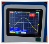
on the rev 3.1 board, i'm getting 12.8Vrms output
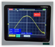
on the rev 2.1 board, same setup, i'm getting about 21.4Vrms before i start to clip. note the volume knob is about 60% when this happens. as i push higher, the signal begins to clip and get choppy, and any higher than about 24-25Vrms, i hit some sort of limiter and it shuts down
to get the max input sensitivity, on the rev 2.1 board, i maxed the volume on the amp, put E30 to -25dB, and pushed the volume up on the DAC until i hit 21.4V which occurred at -10.5dB on the DAC which measures 0.608Vrms of line output
since i have no way to get greater than 2Vrms of line output, i cannot get the required line voltage it to max the rev 3.1
so it appears that in order to get max output from the A04:
rev 2.1 = 0.608V line input
rev 3.1 = unknown, >2V however
so they changed something in the gain structure or the PFFB
when i reached out to aiyima, this was their response
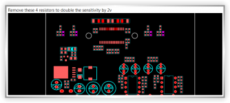
they also said "If two removed resistors are replaced in this position, the sensitivity will increase again by 1.8 times" with this picture
i have yet to attempt these modifications, nor do i know which one i should do: remove the 4, or adjust the 2
i'd likely start by removing the 4 since they never gave me the new resistor values for the second suggestion they sent
so it appears people have two options. have a DAC that outputs more than 2Vrms (which i'm not aware of many that do), or make these mods to get their power back
rev 3.1 getting 40W@4ohm and 19W@8ohm (12.8Vrms)
vs
rev 2.1 getting 110W@4ohm and 55@8ohm (21Vrms)
Attachments
Last edited:
This has been discussed before, search posts with gain structure and what happens at the balancing x2 gain preamp section around the OPAs.
Shouldn't be a prob though for most people unless very unsensitive LS or low source output, cold be better for sound (slightly if ever).
More worried by the fact that if they moved to unitary gain in the preamp section that means a cap is no more needed, so they probably removed it. If changing the gain back to x2 you need that cap back in foreach channel, so 2 caps if they aren't there anymore. You would find out: no music playing otherwise, but no real danger short term.
Good luck
Claude
This has been discussed before, search posts with gain structure and what happens at the balancing x2 gain preamp section around the OPAs.
Shouldn't be a prob though for most people unless very unsensitive LS or low source output, cold be better for sound (slightly if ever).
More worried by the fact that if they moved to unitary gain in the preamp section that means a cap is no more needed, so they probably removed it. If changing the gain back to x2 you need that cap back in foreach channel, so 2 caps if they aren't there anymore. You would find out: no music playing otherwise, but no real danger short term.
Good luck
Claude
thanks claude!
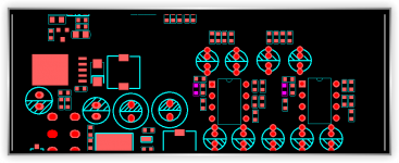
i went ahead and removed the 4 resistors as indicated by aiyimas first suggestion
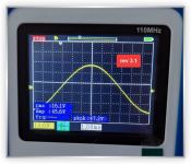
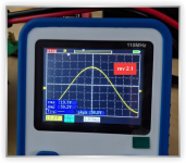
i'm now getting 16.1-17Vrms of CLEAN output (depending on how nit pity you want to get)
from 17 to 20.4Vrms the top of the waveform gets a little wiggly as we hit clipping right about 20.8Vrms (identical to the rev 2.1 board)
so a nice improvement
so we went from 12.8Vrms with 2Vrms input (unable to clip with most DACs) ~20W@8ohm
to
17Vrms ~36W@8ohm of clean power, only requiring 1.1Vrms input, which most if not all DACs can achieve!
pushing it, you can go to 20.4Vrms ~55W@8ohm with 1.35Vrms input, which again, is achievable by most if not all DACs before things head to clipping
now, the rev 2.1 board stays clean the entire way to clipping to 20.8Vrms, so the rev 2.1 board is still superior for sure
provided some pics of the upper end of each of them
Attachments
Last edited:
- Home
- Amplifiers
- Class D
- Aiyima TPA3251 Modification Build Thread!