Hi Nerone,
No problem... I suggest you try to find resistors with low tolerance (make that 1% or less) and low ppm (variation with heat amongst other things also due to current variatons through it).
A shop should know what tolerances and ppm mean and assist you if needed.
Good luck
Claude
No problem... I suggest you try to find resistors with low tolerance (make that 1% or less) and low ppm (variation with heat amongst other things also due to current variatons through it).
A shop should know what tolerances and ppm mean and assist you if needed.
Good luck
Claude
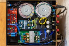
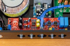
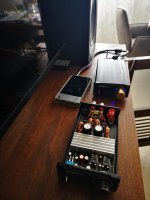
Thank you ! Nothing supernatural you know. With Claude, we decided to go for horizontal bi-amping. Both amps are tweaked as he described throughout this thread. Add some other external elements to drive them: filters, 'superpot', pot... And finally the assembly in the casing, with imagination, tricks, patience and care. DIY they said !
Have a try, step by step, and enjoy 🙂
Have a try, step by step, and enjoy 🙂
xhitespirit I can see you implemented the PO89ZB board. Did you change any of the values for the higher current required here?
Hi Lilolee,
Responding on Gilles behalf, probably easier...
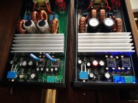
No, we didn't implement PO89ZB, these boards are different. Mark's SMPS filter is not suited for high current appications, and although we probably don't need a high current PS with the high efficiency speakers we currently run, especialy considering we have 2 filters (one in front of each poweramp), we decided to play safe and also future compatibility with other LS that may really need the power of the 2 Aiyima amps.
Therfore, we used a filter of my own. It is also a RLC filter, but only one stage instead of 2 in Mark's case, and twice the current rating of PO89ZB. Fc is also very different; much lower, to compensate somewhat for the single stage. Admittely L is also damped for its critical frequency, protection diode is in, so general layout is indeed very close to say one half of Mark's filter.
Gilles has 2 of these home made filters, on in front of each of his poweramp.
I hope this helps
Claude
Responding on Gilles behalf, probably easier...
No, we didn't implement PO89ZB, these boards are different. Mark's SMPS filter is not suited for high current appications, and although we probably don't need a high current PS with the high efficiency speakers we currently run, especialy considering we have 2 filters (one in front of each poweramp), we decided to play safe and also future compatibility with other LS that may really need the power of the 2 Aiyima amps.
Therfore, we used a filter of my own. It is also a RLC filter, but only one stage instead of 2 in Mark's case, and twice the current rating of PO89ZB. Fc is also very different; much lower, to compensate somewhat for the single stage. Admittely L is also damped for its critical frequency, protection diode is in, so general layout is indeed very close to say one half of Mark's filter.
Gilles has 2 of these home made filters, on in front of each of his poweramp.
I hope this helps
Claude
hello, could you point me towards someone or a list of parts i can buy? i am trying to do these mods but do not have the time to read through every page! i just need to know the values im not interested in bypassing the op amps or external power supply. but everything else i would like to do. is there a list somewhere? thanksHi Lilolee,
Responding on Gilles behalf, probably easier...
No, we didn't implement PO89ZB, these boards are different. Mark's SMPS filter is not suited for high current appications, and although we probably don't need a high current PS with the high efficiency speakers we currently run, especialy considering we have 2 filters (one in front of each poweramp), we decided to play safe and also future compatibility with other LS that may really need the power of the 2 Aiyima amps.
Therfore, we used a filter of my own. It is also a RLC filter, but only one stage instead of 2 in Mark's case, and twice the current rating of PO89ZB. Fc is also very different; much lower, to compensate somewhat for the single stage. Admittely L is also damped for its critical frequency, protection diode is in, so general layout is indeed very close to say one half of Mark's filter.
Gilles has 2 of these home made filters, on in front of each of his poweramp.
I hope this helps
Claude
I have the same idea of the previous post, it's possibile to have a summary of the modification? I suggest to keep it updated and post it on the first page!
I also need an advive about the smps suggested.
Thanks in avdance.
I also need an advive about the smps suggested.
Thanks in avdance.

Sorry guys, there is no summary of my mods: there are posts as there was a benefit understanding what is behind and what choice to make. There was a list of mods initialy, but that may need to be updated. Also, there might be other upgrades, I haven't started this thread and there are other posters.
No time for this as I moved on, but if you don't want to read it all (which I can understand), why don't you use the advanced search function and look at my posts in this thread? Dead easy,far less to read and all infos inclusive parts used and why are inside.
Have fun
Claude
No time for this as I moved on, but if you don't want to read it all (which I can understand), why don't you use the advanced search function and look at my posts in this thread? Dead easy,far less to read and all infos inclusive parts used and why are inside.
Have fun
Claude
Hi Lilolee,
I am away and haven't access to the BOM, but it is dead easy and was just a try.
Coil and its bypass R were respectively 1,5H and 1k.
Small resistance in front of them was 0.05R (5W)
Cap at the output was 3000uF
I used this coil:
https://www.mouser.fr/ProductDetail/Bourns/RLB0912-1R5ML?qs=AC4ivEYFOTD3a6GI6b1NpQ==
And this cap
https://www.mouser.fr/ProductDetail/Nichicon/UBY1V302MHL?qs=j%2B1pi9TdxUbVVwz3LHQ14Q==
I hope this helps
Claude
Guys, without reading all thread, you can find a summary of easy mods to start with in this post from Claude:
https://www.diyaudio.com/forums/cla...modification-build-thread-15.html#post6421245
If it can help !..
Gilles.
https://www.diyaudio.com/forums/cla...modification-build-thread-15.html#post6421245
If it can help !..
Gilles.
The latest project. Amplifier 2.1 class D. Front AIYIMA A04 TPA3251. Subwoofer L15D-SMD. It remains to buy potentiometer knobs.
Attachments
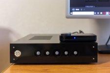
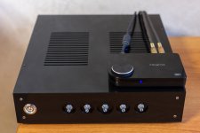

The latest project. Amplifier 2.1 class D. Front AIYIMA A04 TPA3251. Subwoofer L15D-SMD. It remains to buy potentiometer knobs.
wow thats amazing. is the a04 modified?
Thank you! Yes. Here's a description. https://www.diyaudio.com/forums/class-d/276982-tpa3251d2-194.html#post6449746
The OPA2132PA is already installed.
The OPA2132PA is already installed.
Hi guys.
I bought some time ago a second unit. This one is not as good. It hasn't the power the fist one has. I've took out the thermal bracket and there was paste on the pins. After cleaning it, it has more power but not as much as the first one I bought. There is a big difference is power.
What can be the difference? I have changed the opas. The sound is better but the power is the same.
Thanks
Attachments

Compare the values of the resistors near the chips on the two amplifiers. Replace the 10K to 20K resistors. 2700 ohms to 100 ohms at the chip output. (solving the problem from the internet)
I don't know what they might have changed during production, but the first thing is to dertermine whereas you are really down on power... or if it just gain sructure discussion (when the pot is in the same position, less volume, but that doesn't say you can't push it to max, it acts just as an offset so to speak off at your user level).
The 04 has with its AOPs in front of the power chip a balancing stage. It is not as recommended by TI's paper, as it also has a gain of 2 (and not 1). Perhaps they found out... That means different resistors and possibly getting rid of one cap, but I doubt they went that far in savings (?). If the "problem" is that, then you don't lose any max power unless you are playing the volume at max level and bottoming your pot, it is just the gain structure is different (and probably a tad better re sonics)
Good luck
Claude
- Home
- Amplifiers
- Class D
- Aiyima TPA3251 Modification Build Thread!