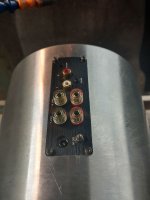
Hello audio friends, I have a question about moving the power/toggle switch to the rear panel and moving the volume pot as well.
I'll be re-designing the case for myself and a friend to be absolute minimalist, so these two need to be relocated.
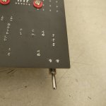
The volume pot relocate looks straight forward with 6ea solder points. However the power switch unknown, is if I have to re-solder the two housing pins back into their location (on back of PCB), or are they just for stabilization of the switch housing?
Thank you all, I really have enjoyed reading all the mods being done to these and will follow suit with this case re-design.
I'll be re-designing the case for myself and a friend to be absolute minimalist, so these two need to be relocated.
The volume pot relocate looks straight forward with 6ea solder points. However the power switch unknown, is if I have to re-solder the two housing pins back into their location (on back of PCB), or are they just for stabilization of the switch housing?
Thank you all, I really have enjoyed reading all the mods being done to these and will follow suit with this case re-design.
Attachments
Last edited:

Usually the chassis of such switches is not connected to the switch pins. To be sure, I'd suggest checking for connection/continuity between the big lugs and the electrical pins of the switch, after you have removed it. That said, the metal cases of switches can still form part of the shielding and/or safety earth, if they are grounded.
Though: extending wires to the switch, and especially to the volume pot, can offer more opportunity for noise to be induced into the circuit. For example, some amplifiers have long mechanical shafts from the front panel to the switches and pots, in order to avoid either longer leads or having the switches/pots in places less optimally placed for noise. In some cases the extra impedance of the extension wires can even change the balance of the circuit. So essentially, you would need to test in order to check this change in form doesn't affect the function too badly.
Though: extending wires to the switch, and especially to the volume pot, can offer more opportunity for noise to be induced into the circuit. For example, some amplifiers have long mechanical shafts from the front panel to the switches and pots, in order to avoid either longer leads or having the switches/pots in places less optimally placed for noise. In some cases the extra impedance of the extension wires can even change the balance of the circuit. So essentially, you would need to test in order to check this change in form doesn't affect the function too badly.
Ok, thank you. I'll check all that before disassembly.
Is there a shielding wrap for the wire extensions I should try?
Is there a shielding wrap for the wire extensions I should try?
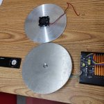
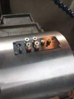
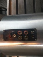
Ok, the rewire/relocate worked great. No audible noise introduced, but will still look into some shielded wires. I used solid core 18g copper wire for the power switch relocated right above DC input.
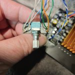
For volume pot, I simply used twisted pairs of multistrand copper from a CAT5 cable.
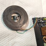
Mic'ing the volume pot for assembly to a large interface disc, I will probably resolder the wires directly to the pot for maximum clearance.

And I cannot hear any deleterious effects on the volume pot when centered within a large magnet. I had to see if this would affect the sound as I may need to use a much smaller neodymium magnet in the large diameter dial design.
For volume pot, I simply used twisted pairs of multistrand copper from a CAT5 cable.
Mic'ing the volume pot for assembly to a large interface disc, I will probably resolder the wires directly to the pot for maximum clearance.
And I cannot hear any deleterious effects on the volume pot when centered within a large magnet. I had to see if this would affect the sound as I may need to use a much smaller neodymium magnet in the large diameter dial design.
Attachments
Last edited:
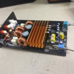
This amp doesn't get very hot, but will be in a vented all-billet alloy enclosure with capability for a small 12VDC brushless fan bottom-mounted.
Question is, does this A07 board have a place to add a fan from 12V?
Question is, does this A07 board have a place to add a fan from 12V?
Last edited:
I don't think so, but if you use a SMPS to power the A07 you could hook the fan up using something like this and have it control the fan based on internal temperature.
Side note, now that you have removed the volume pot board, it's best to replace it altogether with a higher-quality, audio pot. I have this amplifier and it's a pretty big pain in the neck. Scratchy when it's moved around too frequently, and at any setting lower than 10-12 o'clock there's a volume imbalance 🙂
Side note, now that you have removed the volume pot board, it's best to replace it altogether with a higher-quality, audio pot. I have this amplifier and it's a pretty big pain in the neck. Scratchy when it's moved around too frequently, and at any setting lower than 10-12 o'clock there's a volume imbalance 🙂
Maybe something like thisvolume pot suggestion?
https://www.ebay.com/usr/lasercollection?_trksid=p2047675.m3561.l2559
TPA3255 (Part 2) or L12/2? - YouTube
From minute 17 onwards he shows an Aliexpress fan thermoswitch and how to hook one up I believe.
As for potentiometer, you can't really go wrong with (genuine) Alps.
A more exotic option, but mentioned previously on the forum is the DACT 21-23-24 step ladder attenuators.
From minute 17 onwards he shows an Aliexpress fan thermoswitch and how to hook one up I believe.
As for potentiometer, you can't really go wrong with (genuine) Alps.
A more exotic option, but mentioned previously on the forum is the DACT 21-23-24 step ladder attenuators.
Would these be good to piggy-back off the 36V power supply that came with the A07?...
https://www.amazon.com/Converter-Ad...2lkZ2V0TmFtZT1zcF9waG9uZV9zZWFyY2hfYXRm&psc=1
https://www.amazon.com/Converter-Ad...2lkZ2V0TmFtZT1zcF9waG9uZV9zZWFyY2hfYXRm&psc=1
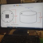
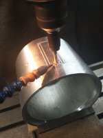
Started designing my minimalist amp case with integrated volume dial.
Grafting in the TPA3255 amp board with 36V 5A power supply for the prototype.
Hopefully an inexpensive GanFET DIY board becomes available soon. A Hypex NCore would be too easy to drop in surely.
Grafting in the TPA3255 amp board with 36V 5A power supply for the prototype.
Hopefully an inexpensive GanFET DIY board becomes available soon. A Hypex NCore would be too easy to drop in surely.
Attachments

Ok, after further research I purchased a couple ALPS 50KAX2 potentiometers for fitment and quality.
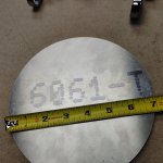
Large diameter billet casings are being trued and programmed on CNC lathe tonight.
Large diameter billet casings are being trued and programmed on CNC lathe tonight.


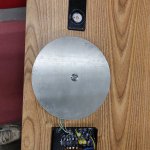
Back on the project. Had to wait 'til I had CNC mill time and a large 8" mill vice....
My dial mechanism works like a champ, just have to make that look pretty next...
My dial mechanism works like a champ, just have to make that look pretty next...
Attachments

Last edited:
- Home
- Amplifiers
- Class D
- Aiyima A07 question for case re-design