You could have a main power switch to turn on the transformer but you could also have independent power switching for the secondaries. you could put a switch on the HV secondary and a mains switch so that the heaters turn on with the main power and then switch on the HV after a minute.
maybe the image uploaded...
guess not...
was wondering if this is capable of doing what you described? so far i'm using all rotary switches and it would save a few dollars since already purchased.
not sure why c1 and c2 are present...
Attachments
you can use that one...IIRC you can sequence switch to be off, on1(heaters), on1(heaters) and on2(HV)
heater & B+ switch ; octal tube range of dimensions
Current plan is to put heater on main power switch with a separate for high voltage.
DPST for the high voltage?
SPST for the mains?
I should have read closer that it was for switching separate transformers on.
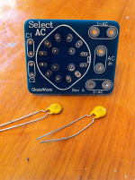
Does anyone know why the caps are used? I guess from someone that doesn't know would be they need to charge when powered on and that might reduce pop?
If this is the purpose of the caps, can I do something like that for the high voltage switch, probably on a tiny board?

What is done with the purple wire?
The transformer arrived, didn't come with two blue, two green but instead with a brown and orange in place of the second b/g.
I did get this response about the switch use the way I had hoped it would work.
"The switch requires two transformers. Let me think about this one, as there might be a way you could place the primaries in series (as if you lived in Europe and had 240Vac, but you don't so the secondaries would only put out half the AC voltage) and then on the third position, the primaries would be placed in parallel."
Hopefully that helps out anyone that runs into the same problem as I did.
Right now, not sure what I'm going to use for switches.
I did have a preference for matching clean, flat black dials which might have to be abandoned.
Soldering iron returned to mfg for repair so I have time to look at other parts.
Is there much variation in the size of tubes or their bases? It is still possible I will rework the board to use higher mu tubes should I go ahead with F4 project. I ask because the tubes, and possibly part of their bases will project from the top of the chassis and only want to cut holes once and would like to get the size right the first time. I'm not anticipating needing anything to dress up the hole due to a sloppy cut, but might start looking to see what is out there.
I have flexible chassis design, the current plan is to have the sockets 1/2" to 1" (12mm to 25mm) below the top. Is there a noise benefit to having the entire tube (but not the base, or half the base...) partially isolated from the rest of the electronics by having it outside the chassis?
Current plan is to put heater on main power switch with a separate for high voltage.
DPST for the high voltage?
SPST for the mains?
I should have read closer that it was for switching separate transformers on.
Does anyone know why the caps are used? I guess from someone that doesn't know would be they need to charge when powered on and that might reduce pop?
If this is the purpose of the caps, can I do something like that for the high voltage switch, probably on a tiny board?
What is done with the purple wire?
The transformer arrived, didn't come with two blue, two green but instead with a brown and orange in place of the second b/g.
I did get this response about the switch use the way I had hoped it would work.
"The switch requires two transformers. Let me think about this one, as there might be a way you could place the primaries in series (as if you lived in Europe and had 240Vac, but you don't so the secondaries would only put out half the AC voltage) and then on the third position, the primaries would be placed in parallel."
Hopefully that helps out anyone that runs into the same problem as I did.
Right now, not sure what I'm going to use for switches.
I did have a preference for matching clean, flat black dials which might have to be abandoned.
Soldering iron returned to mfg for repair so I have time to look at other parts.
Is there much variation in the size of tubes or their bases? It is still possible I will rework the board to use higher mu tubes should I go ahead with F4 project. I ask because the tubes, and possibly part of their bases will project from the top of the chassis and only want to cut holes once and would like to get the size right the first time. I'm not anticipating needing anything to dress up the hole due to a sloppy cut, but might start looking to see what is out there.
I have flexible chassis design, the current plan is to have the sockets 1/2" to 1" (12mm to 25mm) below the top. Is there a noise benefit to having the entire tube (but not the base, or half the base...) partially isolated from the rest of the electronics by having it outside the chassis?
Attachments
The purple wire is a static shield between the primary and secondary windings.
Put that to ground, it helps keep the noise out.
Put that to ground, it helps keep the noise out.
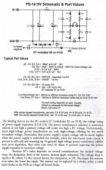
PS-14 heater transformer, getting from 12.6VAC to 6.3VDC
In my stubbornness to stick with matching switches on the front of the preamp, I decided to buy a separate transformer for the heater voltage.
I'll be using the switch above to turn on the transformers. I looked at my notes for going from 12.6VAC to get to 6.3VDC - but the power supply will not get me to 6.3 from there, only options listed for 6.3VDC are 5VAC, 7VAC, or 12VCT.
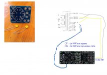
I believe in the above photo there is a mistake on the wiring, I have two 6.3 coming off the original transformer. This ignored the attachment to CT on the board. Correct seems to be the end wires on 1 and 2 in the diagram below, and the striped center wire to CT. Additionally, this would have given me 12.6 when I needed 12.
This week I purchased a 12.6 V Hammond 116n12, 12.6VCT probably a mistake. I haven't hooked it up to test the voltage on each lead. I now have three leads which make sense for the notes in the PS-14 manual.

Back to the problem of 12.6VAC - so I should have purchased a 12VCT? Is there a solution to get this to work? Minimum current needed for 4x 6sn7's?
I purchased a few cheap 6H8C's off of ebay to get started with, but didn't read reviews of them until receiving them. In the market for Tung Sol reissue...
If the heater transformer won't work, I'm in the market for one that can be shipped very fast. It seems the locally available ones do not have enough current. I've spent over 6 hours in traffic over the last two days trying to get parts which were not in stock.
Before I go ahead with wiring the switch I'll post an updated diagram.
In my stubbornness to stick with matching switches on the front of the preamp, I decided to buy a separate transformer for the heater voltage.
I'll be using the switch above to turn on the transformers. I looked at my notes for going from 12.6VAC to get to 6.3VDC - but the power supply will not get me to 6.3 from there, only options listed for 6.3VDC are 5VAC, 7VAC, or 12VCT.
I believe in the above photo there is a mistake on the wiring, I have two 6.3 coming off the original transformer. This ignored the attachment to CT on the board. Correct seems to be the end wires on 1 and 2 in the diagram below, and the striped center wire to CT. Additionally, this would have given me 12.6 when I needed 12.
This week I purchased a 12.6 V Hammond 116n12, 12.6VCT probably a mistake. I haven't hooked it up to test the voltage on each lead. I now have three leads which make sense for the notes in the PS-14 manual.
Back to the problem of 12.6VAC - so I should have purchased a 12VCT? Is there a solution to get this to work? Minimum current needed for 4x 6sn7's?
I purchased a few cheap 6H8C's off of ebay to get started with, but didn't read reviews of them until receiving them. In the market for Tung Sol reissue...
If the heater transformer won't work, I'm in the market for one that can be shipped very fast. It seems the locally available ones do not have enough current. I've spent over 6 hours in traffic over the last two days trying to get parts which were not in stock.
Before I go ahead with wiring the switch I'll post an updated diagram.
Attachments

Last edited:
no you are good with that 12.6V hammond. The resistors R5 and R6 set the output voltage from the regulator.
12.6V will get you 17.76VAC rectified going into the filter then the regulator. If it were me I would set the output voltage to 12.6VDC and run the tube heater pairs in series, it is easier on the regulator to do this. Then each tube in the series of 2 see half the 12.6V or 6.3V.
R5 would be set at 124 ohms from the kit and R6 you would set to a value of 1.13K to output 12.6V from the regulator. To take 17.76V down to 6.3V would be hard on the regulator and it would get hot.
Here is the formula for the output voltage for the regulator:
Voutput = Vref(usually 1.25V) * (1+R6/R5)
so 1.25*(1+1130/124) = 12.64
Sorry - my post above was erroneous
12.6VAC will rectify to 17.76VDC raw that would then get filtered and go to the regulator.
figure a 2-3 volt loss on the diodes and filter you get about 14-15VDC headed to the regulator. Regulated down to 12.6VDC you dont have to dissipate that much heat/energy.
12.6VAC will rectify to 17.76VDC raw that would then get filtered and go to the regulator.
figure a 2-3 volt loss on the diodes and filter you get about 14-15VDC headed to the regulator. Regulated down to 12.6VDC you dont have to dissipate that much heat/energy.
Thanks for the help.
The kit has 124 ohm 1/2w resistor option for R6, option of 1.13K for R5, so backwards from what you suggested. It is a "sale price" kit, and has a few mistakes that have been caught, including a mislabeled R5/R7, will try to figure out what means what.
Should I rely on your calculation for R5/R6 or would you need more information?
I don't have a decent camera, but am wondering what it would look like going through a flat bed scanner ...
Broskie is notorious for mis labeling...don't pay attention too much to R5 or Rwhatever. Look at the schematic and match it with the board. The calculation is right. Match the resistors to their position in the formula and on the board.
never ending ps-14 he11
For r7, as explained in post #17
I have 230vac, which should give 324.3vdc. Originally thought I would run a little hotter than the raw 280V / 250V at tubes but I’ve built the Aikido to for the voltages already mentioned. I went a bit over on transformer size.
I need to drop 44.3V to get down to 280V, I don’t know the mA figure to drop.
r=v/I
r=44.3/I
The kit comes with 11 values of resistors, I’m hoping that close counts or if I need to go with a choke a suggested value would help. If I were to build this based on wild guess it would be the 1.6k resistor.
options provided are:
10, 20, 100, 200, 470 in 1W
1.6K, 2K, 3K, 3.9K, 6.8K, 10k in 3W
More problems...
With the Antec I selected, there is no center tap... so assume I must use full wave bridge. The following page states the voltage limit is 250v for FW Bridge.

I went over one scenario with another member, my notes say to tie the two white and bring to one of the pads with the arrow pointing - AC-HV and tie the two yellow and bring to the other pad. I'm unsure of this, see picture from post on November 15th for output from the Antec transformer. Is this putting 460v on one pad?

I still plan on using the Select AC switch, and while I'm still not sure why there are caps for c1 and c2.
Yes, at this point I'm willing to pay for a completed power supply.
For r7, as explained in post #17
I have 230vac, which should give 324.3vdc. Originally thought I would run a little hotter than the raw 280V / 250V at tubes but I’ve built the Aikido to for the voltages already mentioned. I went a bit over on transformer size.
I need to drop 44.3V to get down to 280V, I don’t know the mA figure to drop.
r=v/I
r=44.3/I
The kit comes with 11 values of resistors, I’m hoping that close counts or if I need to go with a choke a suggested value would help. If I were to build this based on wild guess it would be the 1.6k resistor.
options provided are:
10, 20, 100, 200, 470 in 1W
1.6K, 2K, 3K, 3.9K, 6.8K, 10k in 3W
More problems...
With the Antec I selected, there is no center tap... so assume I must use full wave bridge. The following page states the voltage limit is 250v for FW Bridge.
I went over one scenario with another member, my notes say to tie the two white and bring to one of the pads with the arrow pointing - AC-HV and tie the two yellow and bring to the other pad. I'm unsure of this, see picture from post on November 15th for output from the Antec transformer. Is this putting 460v on one pad?
I still plan on using the Select AC switch, and while I'm still not sure why there are caps for c1 and c2.
Yes, at this point I'm willing to pay for a completed power supply.
Attachments
Are you still using 4 6sn7? Then assume 40mA total. You need to drop about 45v on 40 MA = 45/0.040= 1125. So start with 1.6k and measure voltage.
Have it dropped in, but since I can't find a way to make the Antec transformer work with this I'm stuck.
I can keep searching for a 230VCT transformer or start looking for something close.
I can keep searching for a 230VCT transformer or start looking for something close.
Start using only one of the secondaries...tape the other ones off...I use an antek on a ccda all in one and it works great
Optional coupling capacitors for Aikido Octal
Does anyone have any recommendations for a coupling capacitor?
I purchased the Cornell Dubilier polypropylene 1uF 1000VDC coupling capacitors that were offered with the kit, as well as the switch which would let me select between coupling capacitors for different sound.
Without spending a bunch of money, any recommendations? I don't know what the values are for, just that I am using this for a line stage amplifier for an Adcom power amplifier until I decide on another build to replace it. After some reading oil/paper/foil combo's seem interesting but I'm not able to find them with values similar to the polypropylene ones offered.
I have also read that high end capacitors in this position did not make much of a difference according to one builder.
The second option with the kit was for what I was assuming were for headphone use and I'm not going in that direction now. That option was for Dayton poly coupling capacitors and if memory serves correct they were .47uf and 250V.
Can I do damage to an amplifier or the preamp itself by choosing something with values that are random but between those two ranges?
I used Obbligato Gold 1uF and I am very happy with the results.
The coupling cap determines the -3db knee frequency, higher value causes lower cutoff.
I doubt the value you choose will cause problems unless you choose a ludicrously large value and it allows ultra low frequency in, it will still block DC.
The coupling cap determines the -3db knee frequency, higher value causes lower cutoff.
I doubt the value you choose will cause problems unless you choose a ludicrously large value and it allows ultra low frequency in, it will still block DC.
Last edited:
Are you still using 4 6sn7? Then assume 40mA total. You need to drop about 45v on 40 MA = 45/0.040= 1125. So start with 1.6k and measure voltage.
I made smoke.
The voltage was too high with the 1.6K, in upper 340's so I tried another value for R7 then *POP*
Any recommendations on a power supply other than the PS-14? It is too full of errors, bags of parts that don't match.... I've already spent more on UPS fees than the kit cost. Not to mention about 6 hours of driving looking for parts.
working on a possible virtual windows 98 for running older programs.
I have used 3 ps-3 boards with no issues.
You could breadboard a simple tube PSU with a c-r-c
Like a 5ar4 - 47uF - 100-500ohm - 120uF for starters. Adjust R for voltage drop for 40mA.
Try A\C for heaters
You could breadboard a simple tube PSU with a c-r-c
Like a 5ar4 - 47uF - 100-500ohm - 120uF for starters. Adjust R for voltage drop for 40mA.
Try A\C for heaters
I didn't check after the bang, but I did end up getting the heater voltage to 12.58 -after placing an order with Mouser. That was using the kits capacitors for a fw bridge, even though they are off by a decimal place according to the documentation, even the bags don't list the correct values. While the FWCT is listed as an option for heaters - it will not work - maybe with a 24ish volt transformer, but again I can't trust the documentation.
In my requests for help this thread has gone quite a bit off topic, I simply didn't know that building the power supply was going to provide the biggest challenge. About to pull the trigger on ordering a couple of prototype boards and a handful of smaller ones to test ideas I have. A couple of circuits to switch certain values to use the numbers provided for 6SL7 for V1 / V2. A bit ADD of me when I don't even have a working preamp... looking at a Rotel on Craigslist.
I think using prototype boards to build the circuits will force me to learn more of the calculations.
No luck in getting an old version of Windows to install in Virtualbox on the Mac last night. All this to try the various software from duncanamps, broskie , etc...
- Status
- Not open for further replies.
- Home
- Amplifiers
- Tubes / Valves
- Aikido starter help requested