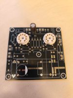
Okay, for the record I will not be hosting an Aikido Noval pcb group buy. Anyone anxiously awaiting this decision is on notice. The good news: 5 boards, available in many colors, can be had with the lead-free HASL option and the slowest shipping method from jlcpcb.com to any location in the US for $5.11 (including PA tax). That's insane.
Once again, many, many thanks to Sadface for making this madness possible!
Once again, many, many thanks to Sadface for making this madness possible!

Hi Tom,You might want to double check that you have enough clearance around the high-voltage lines.
KiCAD includes a tool for calculating the minimum spacing based on the relevant IPC standard.
Tom
I want to ask you about 21st Century Maida Regulator (Rev.3.0 or older) if is used with this circuit, does capacitors C4A and/or C4 are required or not? Is there any benefit of using these capacitors in the circuit? I am referring to the schematic of Aikido is posted in #31.
Many thanks,
bekim
Tom surely can provide a better answer than I can, but in my Aikido I use a tube rectifier, 10uF, the Neurochrome board, 10uF, then bypass R12, C4 and C4A. The unit is dead quiet. But maybe there are technical reasons to do otherwise.
platon.rado:
I'm in process. My Aikido project is competing with two B1 variations (a Rev. 2 and a Korg Nutube), so it may take a little while. I'll post a note and photos when it's finished.
Regards.
I'm in process. My Aikido project is competing with two B1 variations (a Rev. 2 and a Korg Nutube), so it may take a little while. I'll post a note and photos when it's finished.
Regards.
Folks:
I am still largely side-tracked by another project but I have begun populating the Noval boards for my Aikido project and have stumbled on what is likely a dumb question: what is the recommended wattage for R12? I was about to install a 1/2 watt resistor in that position but noticed the footprint is far larger there than those for the other resistors on the pcb. Is this my paranoia at work or did I manage to not make a foolish error?
Many thanks and happy holidays!
Regards,
Scott
I have 3w for R12. It's actually depend on your PS. Without load, it's around 330v and 290v with 4 tubes.
This is my PS configuration for 4x6SN7 to run on both Left and Right.

This is my PS configuration for 4x6SN7 to run on both Left and Right.
R12 has pads such that you can put 2 resistors side by side in parallel for higher dissipation.
The actual dissipation depends on your B+ supply, current through the aikido and the voltage you need to drop to get from your 'raw' B+ to your target b+ at the tubes.
In my case (6SN7).
I am expecting 15mA through each channel
Target B+ at the tubes is 250Vdc
'Raw' B+ is 265Vdc.
R = E/I
= 15Vdc/0.015
= 1K
P= E x I
= 15 x 0.015 = 0.225w for the DC part. Derated by at least x5 = 1.5w
I am running 2x 2k 3w metal oxide resistors in parallel.
Hi @Sadface, I have a question on the cathode resistors. I noticed you selected 470 and 100 ohm values. I was considering going with 680 and 300 ohm. What was your rational selecting 470 and 100 values? Did you want to pull more cathode current on the 6sn7 tubes? I've been spending far too much time thinking about this. 🙂
I received your octal aikido pcb from another thread and am looking to order parts for it.
Thanks,
Tom
I received your octal aikido pcb from another thread and am looking to order parts for it.
Thanks,
Tom
In the Octal all in one manual, which was my build, 680 and 300 are the recommended values for a line stage with 6SN7's and a 300VDC B+. 470 is recommended in the section on using it as a headphone amp. Maybe that's the connection. Headphone usage might need higher bias currents.
LOL, my manual is 470 and 300, work fine without any problem. Suggestion value from 100-1k abd 470-1k
300r default for 12sx7, 6sn7, 6h30pi, and 6sl7
At 100r, the output gain probably 0.02% different, you won't see much different. Should be fine.
According to the table, B+300v can be 243r-1k where the output gain different around 0.01-0.02%
Gain
680r - 20.3dB
470r - 20.4dB
1k - 20.1dB
300r default for 12sx7, 6sn7, 6h30pi, and 6sl7
At 100r, the output gain probably 0.02% different, you won't see much different. Should be fine.
According to the table, B+300v can be 243r-1k where the output gain different around 0.01-0.02%
Gain
680r - 20.3dB
470r - 20.4dB
1k - 20.1dB
I think I've seen a few different manual versions. LOL. I will probably go with 680r/300r at 300v B+. Thanks
I recently discovered my error.
I took my values from the headphone amp section of the Octal manual instead of the linestage section.
At some stage i will update the silkscreen and re-upload the gerbers.
I took my values from the headphone amp section of the Octal manual instead of the linestage section.
At some stage i will update the silkscreen and re-upload the gerbers.
No worries. I think both configurations would work. The documentation was a little confusing. It didn't always specify in the text of the manual whether is was for line or headphone.

Posts related to LTspice moved here:
https://www.diyaudio.com/community/...from-beginner-to-advanced.260627/post-7953160
Hello again.Hello everyone,
Have you ever tried the Aikido configuration with 6AU6 and 5687?
My question to everyone is if any of you, have built the circuit above with 6AU6 and 5687 ( I have many of them in stock). I designed the circuit in a pcb with sprint layout 6 and if it works OK I will send it to China for production. Has anyone dealt with this circuit? I don't use the LT Spice.
I would appreciate any feedback.
Thanks a lot
- Home
- Amplifiers
- Tubes / Valves
- Aikido Noval PCB (or Gerber) Source