I could use some help selecting the superior transformer for an Aikido PP headphone amplifier. I have several 8FQ7, 8GU7, 6n1p, and 6n6p tubes.
Headphones are the Sennheiser HD 6XX (HD650, 300ohm) and possibly a 32 ohm HiFiMan Sundara in the future.
The two output transformers that I am considering are:
VDV-600-32-HPH http://www.trafco.rs/download/VDV-600-32-HPH ENG.pdf
Primary Impedance : Raa 0.6 = [kΩ]
Secondary Impedance : Rls 32 = [Ω]
Turns Ratio Np/Ns : Ratio 4.332 = [ ]
Nominal Power : Pn 3 = [W]
Total Primary DC Resistance : Rip 40 = [Ω]
Total Secondary DC Resistance : Ris 4.3 = [Ω]
Total primary Inductance : Lp 175 = [H]
Primary Leakage Inductance : lsp 0.7 = [mH]
VDV-800-V-HPH https://mennovanderveen.nl/cms/imag...H/2018-10-30_VDV-800-V-HPH_specifications.pdf
Primary Impedance : Raa 0.8 = [kΩ]
Secondary Impedance : Rls 16, 32, 64, 125, 300, 600 Ω = [Ω]
Nominal Power : Pn 1 = [W]
Total Primary DC Resistance : Rip 18 = [Ω]
Total Secondary DC Resistance : Ris 19, 9.5, 7, 5, 4, 3 = [Ω]
Total primary Inductance : Lp 40 = [H]
Primary Leakage Inductance : lsp .04, .08, .2, .7, 1.2, 1.5= [mH]
Which one of these two would be the superior option here? The VDV-800 is flexible but I do not know how much inductance is required or how much Leakage inductance & Ris should be tolerated.
On the other hand the VDV-600-32 has only one tap and presents a 600 impedance for low impedance and a 5600K impedance for 300 ohm headphones. Would this give the Sennheiser even lower distortion or would I run out of milli-watts or require new biasing different than what's in the Aikido manual?
Last edited:
The first one, because it has significantly higher primary inductance … 175 H, compared to 40 H.
With the higher inductance, it will in turn offer better impedance transformation at both the 32-Ω-to–600 Ω end, and the 300-Ω-to–5600 side.
Thing is, for headphones, you will not be running more than a handful of milliwatts for either headphone choice. Simply too dâhmned loud and potentially ear-health-challenging. So, tho' you will want to change the output biasing for pushing a 32 Ω phone, and the same fo the 300 Ω job, the changes may well be only a single top-side or front-side mounted DPDT switch to change out a pair of resistors, once the sweet spot is found.
Use a POT on one leg to start with, and experiment with the 300 Ω headphone. When satisfied, measure its resistance, and select resistors for the 'other side' of the DPDT. Then plug in the 32 Ω phones, and again, fiddle with the biasing. Measure, select, solder into place. Remove the POT.
Anyway, whether this is dubbed entirely sound by the community or not remains to be seen. I prefer the approach as a general rule.
⋅-⋅-⋅ Just saying, ⋅-⋅-⋅
⋅-=≡ GoatGuy ✓ ≡=-⋅
I will go with the second one then. I could always use my computer as a distortion analyzer with a 300 ohm resistor on the secondary and a pot for the biasing.
Then have a selector switch tied to a simple pcb I can create to switch based upon load. Thanks GoatGuy.
Then have a selector switch tied to a simple pcb I can create to switch based upon load. Thanks GoatGuy.
Member
Joined 2009
Paid Member
did I follow this correctly ?
“which one should I pick?”
“pick the first one”
“I will go with the second one then”
? 🙂
“which one should I pick?”
“pick the first one”
“I will go with the second one then”
? 🙂
Last edited:
> significantly higher primary inductance … 175 H, compared to 40 H.
But 40H is > 800 ohms all the way down to 3 Hertz!
At the suggested 0.8k it has a VERY generous inductance for any audio purpose.
But 40H is > 800 ohms all the way down to 3 Hertz!
At the suggested 0.8k it has a VERY generous inductance for any audio purpose.
Well then I'm back to square one. Is there any easy way to compare the two? The VDV-600-32-HPH has a f3 power bandwidth of fu = 14 [Hz].
I cannot see things like phase, effective primary capacitance, insertion loss of the VDV-800-V-HPH. And I don't know how much weight I should give the secondary DC resistance or primary leakage inductance spec. As the leakage inductance goes up the secondary dc resistance goes down and vice versa for each tap.
I do know that single secondaries are often thought of as better but then these are tiny output transformers with a 24 year gap in design dates. Between my Luxman SQ-N100 and Little Dot MKIII OTL I honestly like the transformer output of the Luxman more with headphones. Since both will be out the door soon I am looking for the best replacement as the new tube amplifier will not have a headphone out.
Last edited:
FWIW, I use an "Aikido" style headphone amp using 6N8S into 6N6P OTL capacitor coupled with no problems. Why do you want to use a transformer?
Attachments
Last edited:
For reduced distortion and capability of using 32 ohm as well as 300 ohm headphones. Triodes behave better into a higher impedance right?
Not necessarily. It depends on the topology really.
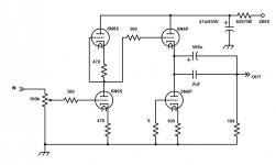
As shown it will drive 32R headphones, but it can only swing 20mA (single ended) into the load so only 12mW, however most 32R headphones are high sensitivity anyway. 100db for 1mW of power isn't that uncommon. I had some JBLs that were almost 120db in other words, plenty loud even with 32R.
As shown it will drive 32R headphones, but it can only swing 20mA (single ended) into the load so only 12mW, however most 32R headphones are high sensitivity anyway. 100db for 1mW of power isn't that uncommon. I had some JBLs that were almost 120db in other words, plenty loud even with 32R.
Since there are many revisions of the Aikido I was getting conflicting information regarding output transformers. John Broskie does have a Tribute opt with a 1200 ohm primary to 32 ohm/300 ohm secondary. It appears that the latest version of the Aikido does need output transformers due to the 50uf Poly RC caps. I'll go with the VDV-800-V-HPH since the specs indicate it will have enough inductance.
New Aikido Stereo Octal PCB & Fancy Interconnects
"The old octal stereo PCB held over 150µF of RC capacitance per channel. This allowed us to get away with making an Aikido push-pull output stage, so that high-impedance headphones could be driven. But with only 50µF of RC capacitance per channel, this option no longer makes sense. The best workaround would be to use a low-winding ratio output transformer. For example, the primary could present a load impedance of 1,200 ohms, which would imply a winding ratio of 2:1 to a 300-ohm secondary; In addition, a low-impedance secondary tap could be added, which would allow the use of 32- to 50-ohm headphones, which implies a winding ratio of 6:1. With such an output transformer, a 10µF coupling capacitor would prove large enough to allow bandwidth below 20Hz."
Hi, i do have a old (2010) Aikido (Rev D) line preamp board, assembled by a friend, and I would like add a headphone output.
I don't have manual and I cant locate it. This gear was given to me as a gift.
I use headphones with 32ohms and 300ohms. Are the transformers of this thread usefull? Should I connect the board's output directly to output transformer?
I don't have manual and I cant locate it. This gear was given to me as a gift.
I use headphones with 32ohms and 300ohms. Are the transformers of this thread usefull? Should I connect the board's output directly to output transformer?
Depend on the tubes. Is it novel 9 pins?
Check out the link below if you have the 9 pins version. That's pretty much the same.
Need Help eliminating hum on a Aikido headphone amp
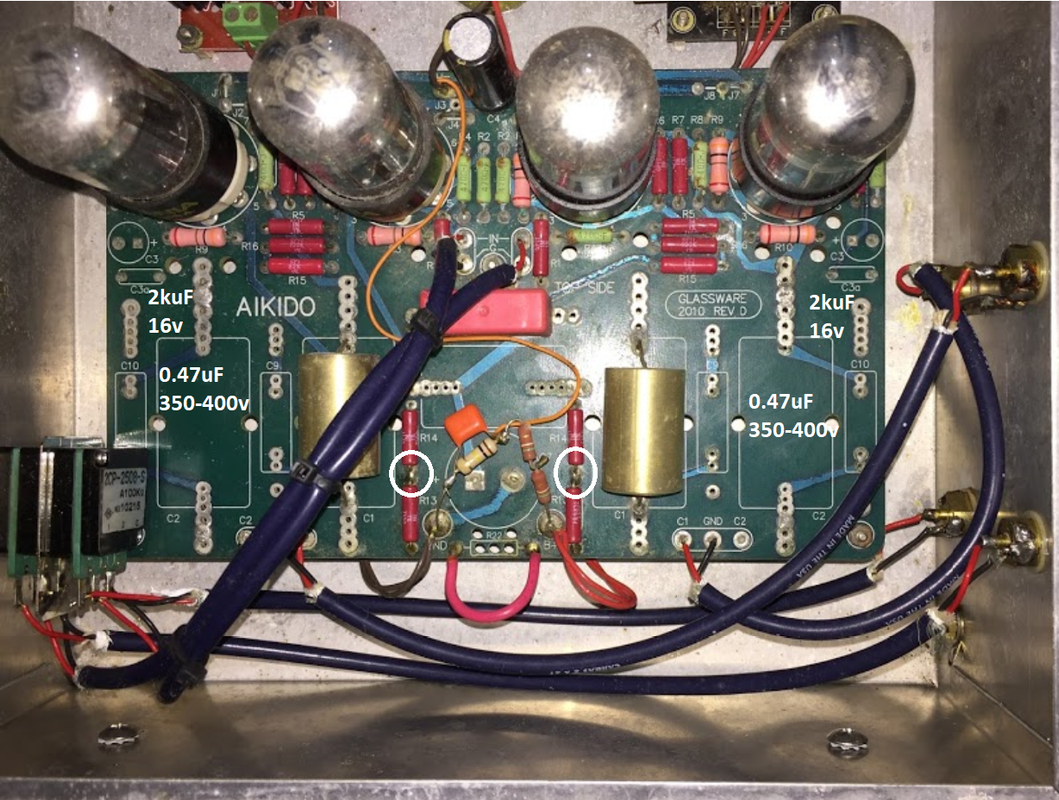
wonsup post #3: check out the image. You want to look at C8, J5, and R13 or R14.
korneluk post #4: R13 disconnect and J5 is connected.
So basically, you want to see if you already have C8 cap or not. If not, you can add that, then use a switch to for J5 and disconnect either R13 or R14 since they're the same value. The switch is support to connect J5 together and disconnect R13 or R14
Check out the link below if you have the 9 pins version. That's pretty much the same.
Need Help eliminating hum on a Aikido headphone amp
wonsup post #3: check out the image. You want to look at C8, J5, and R13 or R14.
korneluk post #4: R13 disconnect and J5 is connected.
So basically, you want to see if you already have C8 cap or not. If not, you can add that, then use a switch to for J5 and disconnect either R13 or R14 since they're the same value. The switch is support to connect J5 together and disconnect R13 or R14
Depend on the tubes. Is it novel 9 pins?
Check out the link below if you have the 9 pins version. That's pretty much the same.
Need Help eliminating hum on a Aikido headphone amp
wonsup post #3: check out the image. You want to look at C8, J5, and R13 or R14.
korneluk post #4: R13 disconnect and J5 is connected.
So basically, you want to see if you already have C8 cap or not. If not, you can add that, then use a switch to for J5 and disconnect either R13 or R14 since they're the same value. The switch is support to connect J5 together and disconnect R13 or R14
Thanks for replying. I'm using 6SN7 tubes. All I need is create a headphone output. Should I use a output transformer? I don't know where and how to install it on the board. I have a headphone Sony CD3000 with 32ohms and another one with 300ohms and I want to be able to play both headphones.

This is kinda complicate.
Link from Aikido 6sn7 Aikido Headphone Amplifier
You need 3 position switch for headphone I think.
On/Off C3
On/Off R14 (need to trace down R13 & R14 since my circle may not correct)
On/Off C1 & C2 (you want to track if these are already jump)
C2 = 0.47uF/350-400v
C3 = 2kuF/16v
C3a may be a jumper for C3
Last edited:
This is kinda complicate.
Link from Aikido 6sn7 Aikido Headphone Amplifier
You need 3 position switch for headphone I think.
On/Off C3
On/Off R14 (need to trace down R13 & R14 since my circle may not correct)
On/Off C1 & C2 (you want to track if these are already jump)
C2 = 0.47uF/350-400v
C3 = 2kuF/16v
C3a may be a jumper for C3
Alright, thank you very much, I will try sort the things out with your data.
Look at those holes between C1 and C2, those may be to setup for the switch, same as C3a because the PCB design as line stage and headphone for easy to configure the switch.
- Home
- Amplifiers
- Tubes / Valves
- Aikido headphone output transformer advice needed