That particular Aikido is not really a "buffer" because it usually has gain. Depending what tube is used in the first stage. From 1 to 30. Yes, if you pick 6AS7 the gain is near unity but the power consumed is frightful.
The output stage only has one triode lowering impedance. Zout is roughly 1/Gm at best but more like 2/Gm because the DC bias resistor is not bypassed. Low-low impedance is NOT the design goal here.
Is intrinsic supply rejection all that important to you? A White Cathode Follower will give lower output impedance on the same tube. Broskie has multiple essays on the WCF.
There are so many ways to do this kind of job. As Bigun pointed out a few posts ago. negative feedback can help get you there.
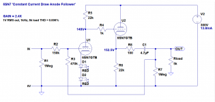
Here's a Broskie 'Constant Current Draw Amplifier' with plate-grid negative feedback added. You could call it a 'Buffered Anode Follower' if you like. Or a 'Buffered Output Voltage Follower'.
Audio signal is fed from the output through R3 back to the input grid.
The amount of negative feedback is derived from the voltage divider formed by R2 and R3. The values chosen for R2 and R3 should result in gain = 2.4X (7.5dB).
The resulting output impedance should be about 150 ohms (maybe lower).
SPICE simulation predicts very low THD into 5k ohms at 1V rms output.
I know, NFB is yucky. Yeah, but what makes a cathode follower a unity gain buffer? That's right. Negative feedback. This is just another way of applying negative feedback to a slightly more fleshed out circuit. And look Ma! No transistors! (OK, a couple of LEDs. But you could replace those with a resistor and capacitor if you like. But that would add another pole inside the NFB loop, which is why the LEDs would be good here. They're good down to DC.)
--
Attachments
Last edited:
This plan gets down to 4 Ohm output impedance. While it shows mini tubes, 6SN7 is same/better for the output tube, 6F5 6SF5 or 6Ф5 is good at the input stage.
PSRR is like 40dB, so it does not need super-clean power. A 3-stage R-C filter may be quite good.
PSRR is like 40dB, so it does not need super-clean power. A 3-stage R-C filter may be quite good.
Attachments
PRR, that is a really nice circuit.
If two channels were to be built on a single chassis, a 6SL7 could be used for TU3, 6SN7 for TU1 and TU2. That would make an all-octal line stage with three tubes. Into a 5k load it looks like you should get solid-state low THD out of it.
Really nice.
If two channels were to be built on a single chassis, a 6SL7 could be used for TU3, 6SN7 for TU1 and TU2. That would make an all-octal line stage with three tubes. Into a 5k load it looks like you should get solid-state low THD out of it.
Really nice.