I’ve built this Aikido Cascade using a 6SN7 from Aikido Cascade & 300B Power Boosted. It’s in use as a input gain stage before my phase inverter.
It measures quite well as far as distortion and amplification is concerned. I cannot find much information about this diagram, so it’s hard to check any of my measurements with it’s design parameters.
I wonder what would be the input and output impedance for instance. For which input level would it be designed? What would be the optimum value for a volume control at the input?
I think I already get full drive with only 0.7 V Peak to Peak, so what would be a good way to lower the amplification without losing the Aikido design philosophy?
Regards, Gerrit
Attachments
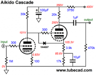
Don't know what the "Aikido design philosophy" is, but if I remember correctly he's big on injecting PS ripple (out of phase) here and there to cancel out the ripple. So this is consistent, you have 2 stages fed from the same B+ and equal currents (5mA). So ripple would be injected into both stages, one inverted.
Other than that it looks like an ordinary 2 stage preamp, should work at low and medium level signals up to the second stage's swing limit. Not sure if the operating point of either stage is ideal, if you measured distortion and are satisfied it should be fine. Not clear what the purpose of the partial cathode decoupling is, perhaps part of the ripple scheme. If not, you can eliminate the cap for a slight reduction in gain.
To lower the gain more seriously is never a good idea after the fact. Best to design it for the desired gain from the beginning. I've never found it necessary to have 2 stages of gain before the PI.
I think I already get full drive with only 0.7 V Peak to Peak, so what would be a
good way to lower the amplification without losing the Aikido design philosophy?
Input R = 1M
Output R ~ 500R
Gain ~ x10
Volume control from 10k to 100k
There's no hum injection/cancellation in this circuit.
If you use a normal audio taper volume control, it will likely end up being
roughly in mid-rotation in a typical system at louder volumes. If you
need less gain, add a resistor from each volume control wiper to ground.
Try using a resistor of roughly 10% of the control's value, and adjust the value to suit.
Last edited:
The mu is 20, and most circuits will yield roughly half of that, so about x10.
You can calculate the gain more exactly, but it doesn't seem necessary for this.
You can calculate the gain more exactly, but it doesn't seem necessary for this.
Yes, that's right. The second stage will have significantly less gain than the first stage, about x5.
No idea why he put that much gain into a line stage, since usually he uses gnfb, but not here.
This circuit is designed mainly for maximum PSRR, but the gain is way too high for line sources,
especially if used with efficient speakers.
The Rout of the line stage will actually be roughly 10k. The previous value was with a cathode follower.
Last edited:
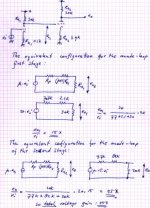
Zout is about 16k. There's 6k inside the 6SN7. There's 3.9k (for audio) under it, times Mu of 20, 80k reflected to plate. Parallel with 20k plate feed makes 16k.
Gain: first stage can give a large fraction of Mu, say 15-18. Second stage has 20k above and >3.9k below so gain something under 5. Total gain something under 80.
SPICE says Zout about 17k and gain about 17 first stage, 52 both stages.
Gain: first stage can give a large fraction of Mu, say 15-18. Second stage has 20k above and >3.9k below so gain something under 5. Total gain something under 80.
SPICE says Zout about 17k and gain about 17 first stage, 52 both stages.
Last edited:
Right. First stage gain about 16, I get a total gain of around 57.
I'd say best thing to reduce gain is skip the second stage.
I'd say best thing to reduce gain is skip the second stage.
Gain of 45-55 is about right IIRC - pretty sure the relevant TubeCAD journal article specifies the gain.
Anyway, I use this circuit as the driver stage for an OTL amp - it has a single 6C33C tube per channel so the gain allows sufficient feedback to get the output impedance down to the required level and output power is just one or two Watts (I use 15ohm high hi-efficency speaker units). It sounds excellent.
6C33C SE-OTL Project - audio-talk
Last edited:
Thanks everyone for the additional information. I will study JoeAlders’s calculations. Perhaps I have to read it 55 times to understand everything.
I will make further measurements and continue testing, probably next week. For now I’m working on the power supply.
Regards, Gerrit
I will make further measurements and continue testing, probably next week. For now I’m working on the power supply.
Regards, Gerrit
- Home
- Amplifiers
- Tubes / Valves
- Aikido 6SN7 Cascade