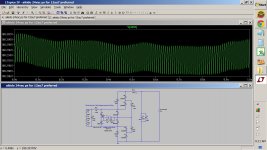
See post 16 above. Below I show the 180 vdc at the top of the resistor R_pre_load which represents a 22 ma draw for the line stage.
Attachments
Last edited:
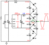
Here's schematic power supply for input 18Vac and output 120V!
What are the values of the components: el.capacitors, diodes and resistors?😕
C2, C6, C7, C8, C9, C10 and C11?
D1, D2, D3, D4, D5 and D6?
R2 =?
R1 = 8.66?🙄
thank you!
What are the values of the components: el.capacitors, diodes and resistors?😕
C2, C6, C7, C8, C9, C10 and C11?
D1, D2, D3, D4, D5 and D6?
R2 =?
R1 = 8.66?🙄
thank you!
Attachments
Last edited:
For 18vac version below. Rest of the components are the same as the 24vac version posted above.
R11 = 10 ohm 1w
R12 = 2k ohm 3w
R11 = 10 ohm 1w
R12 = 2k ohm 3w
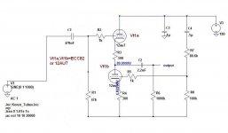
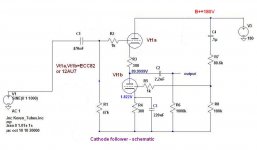
Aikido cathode follower with 24Vac
Hi,
Is this power supply 24Vac can be used to Cadhode follower with ECC82 (see schematic)?🙁😕
What should be the value of the resistor R11 in this case?😕 (see schematic: Aikido 24Vac PS-1 and #16)
Since the breakdown, using two tube (two heater) ECC82 (12au7)?
Thank you!
Hi,
Is this power supply 24Vac can be used to Cadhode follower with ECC82 (see schematic)?🙁😕
What should be the value of the resistor R11 in this case?😕 (see schematic: Aikido 24Vac PS-1 and #16)
Since the breakdown, using two tube (two heater) ECC82 (12au7)?
Thank you!
Attachments
Last edited:
I'd just get a larger wall wart 12VAC output (must be AC), and drive the heaters with that thru the board's power supply to make it DC. And also feed the toroid transformer backwards to get a pair of 120VACs on what were the primaries, not they are secondaries. Then connect them together to get 230VAC centertapped, and use a full wave rectifier circuit to get B+ of around 150VDC after a CRC filter circuit.
Sorry wa2ise I understand you correctly, if you are able to what you said show schematically.I'd just get a larger wall wart 12VAC output (must be AC), and drive the heaters with that thru the board's power supply to make it DC. And also feed the toroid transformer backwards to get a pair of 120VACs on what were the primaries, not they are secondaries. Then connect them together to get 230VAC centertapped, and use a full wave rectifier circuit to get B+ of around 150VDC after a CRC filter circuit.

thank you!
Sorry wa2ise I understand you correctly, if you are able to what you said show schematically.
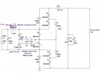
Looks like I was clear as mud... 🙂 Should have said "18VAC wall wart", Something like this:
Attachments

Hello wa2ise!Looks like I was clear as mud... 🙂 Should have said "18VAC wall wart", Something like this:
Two heaters in the Cathode follover (2x12ux7) for stereo!
R11 =? (See schematics)?!🙄
thank you!
Attachments

Last edited:
R11 =? (See schematics)?!🙄
thank you!
Looks like 160 ohms, 5 watt power resistor. Though this value is not at all critical. Be prepared to change this resistor if the heater voltages are too high or low.
I'd change the voltage doubler to just a bridge rectifier, to cut waste heat from dropping the 24V thru the 160 ohm resister (3.6 watts).
Let me know if you'd need more info on that. The bridge rectifier circuit would produce the 24 volts directly.
Last edited:
If you are able to show the bridge rectifier circuit would produce the 24 volts directly.Looks like 160 ohms, 5 watt power resistor. Though this value is not at all critical. Be prepared to change this resistor if the heater voltages are too high or low.
I'd change the voltage doubler to just a bridge rectifier, to cut waste heat from dropping the 24V thru the 160 ohm resister (3.6 watts).
Let me know if you'd need more info on that. The bridge rectifier circuit would produce the 24 volts directly.
thank you!
Here's the bridge rectifier circuit. 18VAC rectifierd and filter capacitor yields 25.8VDC, but we need to take the diode voltage drops into account. This is 2 * 0.7V = 1.4, which makes it 24.4VDC, close enough for heaters. And no need for R11.
Attachments
Last edited:
For 18vac version below. Rest of the components are the same as the 24vac version posted above.
R11 = 10 ohm 1w
R12 = 2k ohm 3w
I put my order in for 12VAC and plan to use my existing 12AU7 tubes, so wanted to make sure that the values above are correct. Is there an online guide for this?
Yakusa, did you ever come right with your hum? Did you make any changes to your transformer wiring? Undecided if I shoudl go transformer or wallwart.
Thx
Neville
- Status
- Not open for further replies.
- Home
- Amplifiers
- Tubes / Valves
- Aikido 12Vac