I've gotten a bit busy over the holidays, but I did check the high density pin header out. It is indeed 2mm spacing, not .07". I have updated board layouts, but I have not had my laptop at work here with me for a while so it may be a moment before I can post updated board layouts.
I hope this work goes on to helps someone somewhere. I am going to look into having a small run of the boards made for people who need replacement drivers, but I have never dived into having pro boards made. I typically stay within my own capabilities on my CNC Bridgeport Boss. Isolation milling these boards alone would pose little to no problems, but not being able to plate vias would make it a challenging experience to hand solder each via and solder every through hole part on top and bottom. I am trying to learn exactly what I have to do to send these out for professional fab, but it will be some time.
Later,
Jason
Some board houses may be able to work from the brd file. The web sites should tell you what they need.
http://www.apcircuits.com/Portals/0/Assets/Downloads/Excellon.pdf?ver=2015-06-03-170520-757
http://www.apcircuits.com/Portals/0/Assets/Downloads/Excellon.pdf?ver=2015-06-03-170520-757
Thanks Perry. I just spent the last hour or so reading over things. I think I am in pretty good shape. I'm thinking of going with OSHpark for the job, simply because they excellent instructions and also turn out some gorgeous boards. I have another unrelated design that I want to send at the same time and I would really like the ENiG finish that they provide.
From what I am reading they accept the .brd files directly. I read through all their supporting documentation and it seems I have all my layers correct, so I'll be contacting them as soon as I have my other project ironed out.
I'll keep you all updated.
Thanks,
Jason
From what I am reading they accept the .brd files directly. I read through all their supporting documentation and it seems I have all my layers correct, so I'll be contacting them as soon as I have my other project ironed out.
I'll keep you all updated.
Thanks,
Jason
Quick update folks, I sent my boards off to fab tonight. I had to re-do my other unrelated design because I had lost the files from the last time I did it. I ended up ordering a crap ton of them. I needed a fair number of the boards for my other project, and it turned out that if I could come up with a total of 100 sq inches of board that I could get them made significantly cheaper. I know this was risky, that I might have errors on the boards, but the quantity order made it cheap enough that I am willing to take the risk.
So far dealing with OshPark has been painless and I submitted the board only a few hours ago and it has already been scheduled for a panel going out in a few days. I am really looking forward to getting these in hand. It will hopefully be the culmination of a lot of work!
I ordered about 10 extra of the daughter boards because it seems they get mangled whenever a shadetree tech tries to repair these. With any luck I got the measurements correct and they will fit the factory boards as well. I have my fingers crossed!
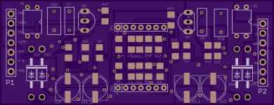
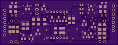
Here are the renders from OshPark in case anyone is interested:
So far dealing with OshPark has been painless and I submitted the board only a few hours ago and it has already been scheduled for a panel going out in a few days. I am really looking forward to getting these in hand. It will hopefully be the culmination of a lot of work!
I ordered about 10 extra of the daughter boards because it seems they get mangled whenever a shadetree tech tries to repair these. With any luck I got the measurements correct and they will fit the factory boards as well. I have my fingers crossed!
Here are the renders from OshPark in case anyone is interested:
Attachments
And they are here! YAY!
A few things almost bit me. The pin header holes for the small daughterboard are almost to small. Like, frustratingly close, but can still get it in 🙂 and I did the same thing for the poly caps. I did the drawings for both of these parts, as well as many others. I used the datasheet sizing, and I must have put in the exact pin size instead of going a bit over. They both fit, but just barely. I am glad they don't have to be scrapped, but time will tell if I made any other mistakes. I am halfway through populating one of them. Have the back side done except for two resistors. They are supposed to be 22R and somehow I managed to buy 2R2... Hopefully nothing else bites me and they work as planned. I have 20 main boards and 30 daughterboards.
Pics for proof 😀 :


Later,
Jason
A few things almost bit me. The pin header holes for the small daughterboard are almost to small. Like, frustratingly close, but can still get it in 🙂 and I did the same thing for the poly caps. I did the drawings for both of these parts, as well as many others. I used the datasheet sizing, and I must have put in the exact pin size instead of going a bit over. They both fit, but just barely. I am glad they don't have to be scrapped, but time will tell if I made any other mistakes. I am halfway through populating one of them. Have the back side done except for two resistors. They are supposed to be 22R and somehow I managed to buy 2R2... Hopefully nothing else bites me and they work as planned. I have 20 main boards and 30 daughterboards.
Pics for proof 😀 :
Later,
Jason
My trusty Hakko 936 iron w/ a small chisel tip. One of these days I will get a hot air station. It is absolutely painful doing this the stubborn way. I looked into getting solder paste and doing them in an oven, but paste is quite expensive and sold in quantities far greater than I need for this project. If I have to step up production for some reason I will have to give it some more thought.
Thanks,
Jason
Thanks,
Jason
Got one done today. Not 100% sure if it works or not. I put it in my mx1500 that has many other issues and although all the signals look good the amp still doesn't work. I'll post more about that in the thread I started about the mx5000 in a second. I'm going to put it in a known good amp when I get a minute.


More to come later!
Jason
More to come later!
Jason
Ok, I think I am going to need a little help here. I pulled a working driver from another amp and put it in my test amp. The amp that I have been using to test does work fine with a stock DLM driver. I have done some more testing, and it looks like my driver is oscillating at 12.5kHz and the stock DLM board is oscillating at ~100kHz. I think the triangle wave is much to low frequency for this to work. I am assuming that somewhere on my board there is a cap that is incorrect. Initially I thought C1 sets the oscillator frequency, but after further investigation, that does not appear to be correct. In circuit, my C1 measures higher than the stock board. I didn't have the proper cap, but I tombstoned a couple in series and got it close to the stock board, but it still oscillates at 12.5kHz.
After further review, I am thinking C2 might actually be the culprit. What stinks is that it is under the daughter board and my daughter board headers were super tight, I am hopeful I can get it apart without damage.
Can anyone else think of anything that might be causing it to oscillate at the wrong frequency? I was never very sure on my initial cap measurements. I am going off a DMM, its the best I have for very low value caps. I know, that doesn't inspire confidence, but it is the tool I have.
Thanks,
Jason
I'm pleased to announce success! Finally!!!
C1 and C2 were both wrong. C2 sets the triangle wave oscillation frequency. I swapped them from the working board and my clone s now oscillating at the same frequency as the original. As close as I can tell these caps are below the range of my meter. I think C2 is somewhere in the neighborhood of 33pF. I bodged in a through hole 33pF on the original DLM and it is back alive and oscillating at ~102kHz, so obviously 33pF isn't perfect, but I will get a few values to try and see if I can make my next tool purchase a good capacitance meter.
I think that C1 is actually part of the FB loop, I have about 100pF bodged in there right now and it seems to work. I think the original might have been 68pF. I will get good measurements once I get a decent meter.
I'll update the schematics and BOM when I get time. For now I am just happy I have one success story!
Thanks,
Jason
Hi Jason,
I ended up here by accident more or less 🙂 I saw you posted this on the PhoenixAudio forum too and was hoping for some more in-depth info like schematics which I found here. My DLM4500 v5 is broken I think. It came out of a SPXL1000 amp from Helix (Made in 'Germany' (aka China)). The power supply seemed to be broken, but I think the root cause of the power supply failure has to do with the DLM4500 board. Either it shorted the rails by turning high and low-side on at the same time, or just turned one rail on fully. Some traces have vaporised due to this, but I am fairly confident that the DLM4500 is the root cause of the smoke 🙂
What I found that is different on the v3 vs v5 boards is only that the v5 uses the DLI4060B chip, which seems to be a Dlogixs special chip. I assume it is just a comparator and op-amp integrated... The power connections on the PCB are marked as -9V and +9V. I think this is the voltage used to control the gates and power the op-amps, right? It could just be the power for the op-amp though.
I think I will have a go at reproducing the board on a piece of vero-card, with the V3 schematics. I have a feeling that this will work.
You did quite a good job at reproducing the boards! It is not that easy to find out all codes and cap values, as you have seen.. Great work!
Joris
Edit: The gates are controlled by the rail voltages, of course! I am quite confident that the Rev3 board will work on 9V just as well as it would on 15V...
Last edited:
Joris, the DLI4060 house chip serves the same purpose the comparator/op amp. I assume it is just two dies in one package. I have another acquaintance from the board with whom I was in contact by email, and he confirmed that the circuit in daughter board from my drawings here worked in place of his daughter board with the house chip.
As far as I can tell all the amps that have these boards use the +/-9 volt supply. The DLM boards themselves are silkscreened +/-15V, I am guessing they are tolerant of 15V supply, but I have yet to see it implemented.
Also, my amps with failed DLM drivers were not failures of the comparator/op amp but of the driver circuits. I believe that both of Adriano's were failures of the house DLI chip, so you might be on the right track. If you start a thread here about your specific amplifier then you will get a lot of troubleshooting help from people who are much smarter than I!
I have also now used my daughter board on a DLM amp that had the bare die epoxied to the board and it worked there as well.
I should have updated this before, but C2 is indeed 33pf and C1 is 1pf. These were both verified by Adriano (the aforementioned member I was working with via email). I will update the schematics when I can get some time.
Good Luck!
Jason
Hi Jason,
I think so as well, as it is very, very expensive to make your own die.. Especially since its function is so simple. I wonder if they went through the trouble of creating their own. I know someone from my education who has access to an x-ray soldering inspection device, which they also use on Chinese chips to see if there is actually dies in them. I might ask him to take a look at the chip 🙂
That sounds quite good! On my amp there are 2 7x12 regulators, followed by a resistor and a zener diode. The voltage is then fed to the DLM board. I have yet to inspect that these voltages are somewhat 9V and present.
Is it okay if I post my progress on this thread? As it is somewhat related and I will probably end up replacing the DLI4060 with a TL072 and comparator... Maybe a nice addition to fix the REV5 boards too, if more people are looking to fix their amp.
It will take some time though, I have a lot of projects ^^
Joris
Absolutely, post it up, I have no problem with it. I had hoped this little project will help other than just myself.
I also have ten extra of the op amp/comparator daughter boards. I ordered extra because they always get mangled. If you want a few, shoot me a PM and we can work something out.
Thanks,
Jason
I also have ten extra of the op amp/comparator daughter boards. I ordered extra because they always get mangled. If you want a few, shoot me a PM and we can work something out.
Thanks,
Jason
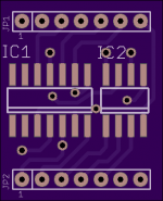
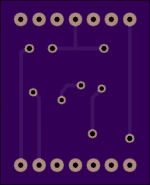
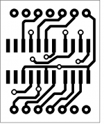
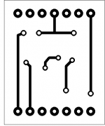
I had forgotten that I never posted the DIY etching templates for the corrected headers on teh daughter board. I recently had a gentleman PM me requesting the fixed templates for the daughter board. They are attached below. The bottom side is mirrored and the overall dimensions should still be .65x.8
Thanks,
Jason
Thanks,
Jason
Attachments
Thank you, Jason! This is actually useful as in my case for example the actual fault was in the ICs after all.
One minor thing and a note to anyone who would use this template - you can't flip the back side as the pcb will not match the ICs pinout, what you really want is to flip the front side.
So both pictures above should be flipped to match the real pcb layout.
One minor thing and a note to anyone who would use this template - you can't flip the back side as the pcb will not match the ICs pinout, what you really want is to flip the front side.
So both pictures above should be flipped to match the real pcb layout.
Last edited:
Hi! I would have a DLM4500 too.
My problem with it is that I don't think the phase is right, it opens the two fets in the same time.
My problem with it is that I don't think the phase is right, it opens the two fets in the same time.
An externally hosted image should be here but it was not working when we last tested it.
An externally hosted image should be here but it was not working when we last tested it.
2 things
1.
Please don't post in a repair thread that was started by someone else unless you are trying to help them.
Start a new thread if you need help with a repair of your own.
2.
To upload photos click the following:
Go Advanced
Manage Attachments
Browse
Upload
Repeat as necessary
Preview post to see how the post will look.
Click Submit Reply to send it to the forum.
- Home
- General Interest
- Car Audio
- Again with the Dlogixs DLM4500