If you haven't taken this thing out back ans shotgunned it to death yet...
Remove all 3 muting transistors. Power up the amp (all transistors clamped down to prevent overheating) and monitor the DC voltage on pad 3 of the muting transistors in the audio section. What does the voltage go down to?
Does it remain there as long as the amp is on (longer than you've left it when the mute circuit acted strangely)?
I've certainly considered doing that to it! At this point determination to fix it has set in though.
Erratic would best explain the readings I got. The voltage eventually dropped to -16.5v after roughly 15 minutes of play. To explain the erratic part of it...it doesn't hold there, it bounces up and down continuously(going back up as far as -8.5v). The voltage was doing that entire time through out the testing...it wasn't a continual drop but up and down. Also, at one point in the middle of testing, I was getting different readings from the two, one being at -6.5v(right side in pic) the other at -2.5v.(left side in pic). Given what you said earlier about negative voltage on this circuit... upon turning the amp on, the readings were +2.5v but immediately dropped into the negative range. Hoping you can make something out of it all...
Erratic would best explain the readings I got. The voltage eventually dropped to -16.5v after roughly 15 minutes of play. To explain the erratic part of it...it doesn't hold there, it bounces up and down continuously(going back up as far as -8.5v). The voltage was doing that entire time through out the testing...it wasn't a continual drop but up and down. Also, at one point in the middle of testing, I was getting different readings from the two, one being at -6.5v(right side in pic) the other at -2.5v.(left side in pic). Given what you said earlier about negative voltage on this circuit... upon turning the amp on, the readings were +2.5v but immediately dropped into the negative range. Hoping you can make something out of it all...
Attachments
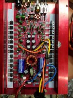
After changing only the diodes only, I monitored the voltage for approximately 15 mins. In that time the max the voltage dropped to was -1.89v on the right and -1.86v on the left. It held there steady and dropped to that voltage steady. The erratic behavior seems to be gone.
Confirm:
0 ohms between any secondary side transformer winding and the striped side of the diode.
0 ohms from the other end of the diode to the 100k resistor.
0 ohms between the second end of the 100k resistor, the negative terminal of the cap and the gate pad for at least one of the muting transistors in the audio section.
I have some questions:
Which diode are you referring to? One of the two I just replaced or both?
Which are the secondary side transformer windings?
Which end of the 100k is the second end?
Also, when checking the diode/diodes(non striped end) to the 100k transistor, does it matter which end of the resistor? (I'm getting different readings from the two ends of the resistor).
Not knowing that I did check it all(using all transformer windings and on both sides of the resistor). I am getting ohm readings either way. Knowing the answer to the above questions I can give you those readings.
Are all muting transistors out of the circuit?
The secondary windings are the transformer windings on the side of the transformer near the muting components. Do you have a 0 ohm connection between those windings and the striped end of the diode connected to the 100k resistor?
The secondary windings are the transformer windings on the side of the transformer near the muting components. Do you have a 0 ohm connection between those windings and the striped end of the diode connected to the 100k resistor?
You ain't going to believe what's been causing all of the problems.
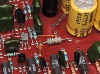
The black cap for the positive regulated voltage leaked (conductive) electrolyte that leaked positive voltage from the positive supply to the mute drive, preventing it from going down. Clean the area with acetone and a cotton swab between the cap and the pad indicated by the arrow.
The black cap for the positive regulated voltage leaked (conductive) electrolyte that leaked positive voltage from the positive supply to the mute drive, preventing it from going down. Clean the area with acetone and a cotton swab between the cap and the pad indicated by the arrow.
Attachments
Last edited:
- Status
- This old topic is closed. If you want to reopen this topic, contact a moderator using the "Report Post" button.
- Home
- General Interest
- Car Audio
- Again needing help fixing Orion HCCA 225 Digital Reference